Spark plug
- Summary
- Abstract
- Description
- Claims
- Application Information
AI Technical Summary
Benefits of technology
Problems solved by technology
Method used
Image
Examples
first embodiment
A. First Embodiment
[0030]A-1. Structure of Spark Plug
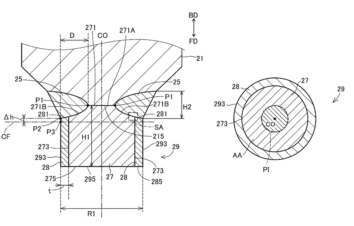
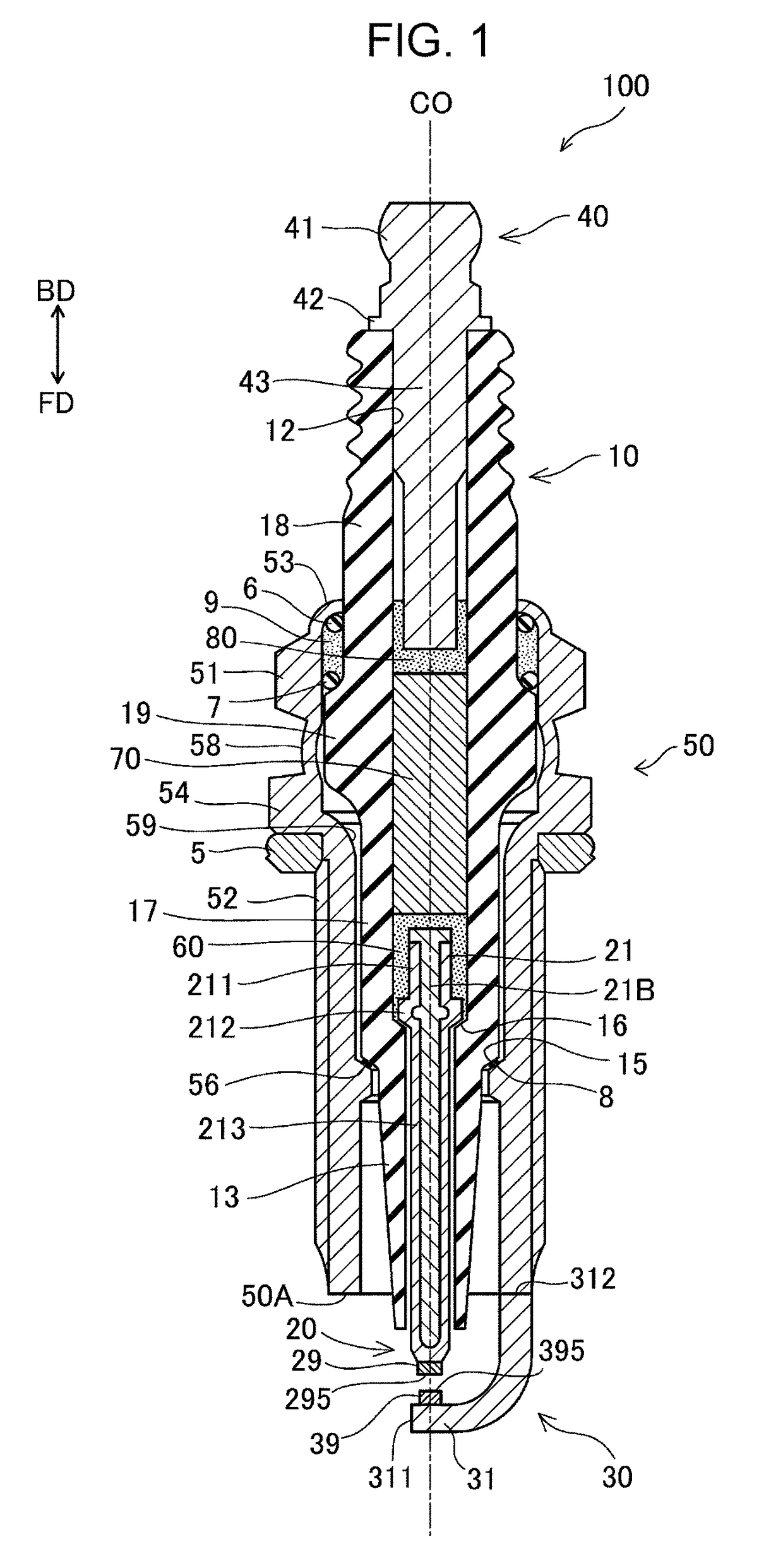
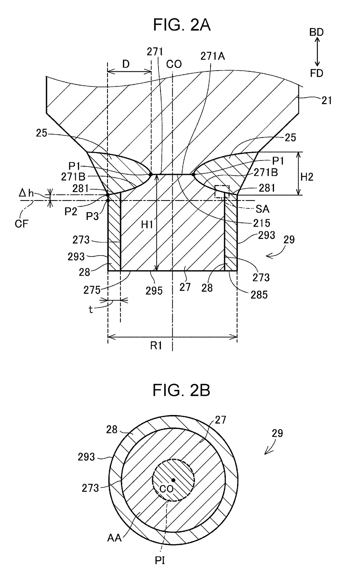
[0031]FIG. 1 is a sectional view of a spark plug 100 according to an embodiment. The one-dotted chain line in FIG. 1 indicates an axial line CO of the spark plug 100. A direction parallel to the axial line CO (up-down direction in FIG. 1) may be referred to as an “axial line direction”. A radial direction of a circle centered at the axial line CO may be simply referred to as a “radial direction”. A circumferential direction of a circle centered at the axial line CO may be simply referred to as a “circumferential direction”. The down direction in FIG. 1 may be referred to as a “forward direction FD”, and the up direction in FIG. 1 may be referred to as a “backward direction BD”. The lower side in FIG. 1 is referred to as a “front side” of the spark plug 100, and the upper side in FIG. 1 is referred to as a “back side” of the spark plug 100. The spark plug 100 includes an insulator 10 serving as an insulator, a center electrode 20, ...
second embodiment
B. Second Embodiment
[0073]FIGS. 6A and 6B are views illustrating a structure around a front end of a center electrode of a second embodiment. FIG. 6A is a sectional view of a portion around a front end of a center electrode taken along a plane including an axial line CO. In the second embodiment, a center electrode tip 29b is used instead of the center electrode tip 29 of the first embodiment. In this center electrode tip 29b, a side surface 273b of a tip body 27b, a surface (front surface) 275b on the first discharge surface 295b side, and an opposite surface 271b disposed on the opposite side of the first discharge surface 295b are covered with a cover layer 28b. Therefore, in the second embodiment, in addition to the side surface 293b of the center electrode tip 29b, the first discharge surface 295b is also formed by the cover layer 28b. This center electrode tip 29b can be prepared by forming an IrAl intermetallic compound film, by the aluminizing process, on a base prepared in ...
third embodiment
C. Third Embodiment
[0078]FIG. 7 illustrates a sectional view of a portion around a front end of a center electrode of a third embodiment taken along a plane including an axial line CO. Unlike the first embodiment, since the welding depth D in the third embodiment is sufficiently large, a welded portion 25c reaches a position intersecting the axial line CO. Therefore, the welded portion 25c has, for example, a substantially columnar shape. The entire opposite surface 271 of a center electrode tip 29 forms a contact portion that is in contact with the welded portion 25c, and a non-contact portion that is not in contact with the welded portion 25c is not present. Other structures are the same as those of the first embodiment.
[0079]In the third embodiment, since a non-contact portion is not present, a projection image to be projected on a particular section CFc is also not present. Therefore, in the third embodiment, the area Sb of the projection image of the non-contact portion is zero...
PUM
 Abstract
Description
Claims
Application Information
 - R&D
- Intellectual Property
- Life Sciences
- Materials
- Tech Scout
- Unparalleled Data Quality
- Higher Quality Content
- 60% Fewer Hallucinations
Browse by: Latest US Patents, China's latest patents, Technical Efficacy Thesaurus, Application Domain, Technology Topic, Popular Technical Reports.
© 2025 PatSnap. All rights reserved.Legal|Privacy policy|Modern Slavery Act Transparency Statement|Sitemap|About US| Contact US: help@patsnap.com


