Zone select stage tool system

a technology of zone select and tool system, which is applied in the direction of sealing/packing, borehole/well accessories, construction, etc., can solve the problems of difficult to ensure the entire annulus is cemented, undesirable or ineffective cementing from the top or bottom of the casing,

Active Publication Date: 2018-01-02
WEATHERFORD TECH HLDG LLC
View PDF46 Cites 8 Cited by
  • Summary
  • Abstract
  • Description
  • Claims
  • Application Information

AI Technical Summary

Benefits of technology

[0035]For its part, the closure sleeve is movably disposed in the first internal bore at least from an initial position to a closed position relative to the exit port. In this way, when cementing through the open tool finishes, a plug deployed downhole can land on a seat in the closure sleeve, and applied fluid pressure in the tool's bore against the seated plug can close the closure sleeve relative to the housing's exit port. In other arrangements, a secondary closure mechanism on the tool can move the closure sleeve from the initial condition to the closed condition. The secondary closure mechanism can be used in addition to the seated plug or can be used instead of the seated plug.
[0038]Preferably, a second or intermediate sleeve is used in the housing's bore and has rotational catches on each end. When the closure sleeve moves closed, the intermediate sleeve is also moved to engage between the catches on the end of the closure sleeve and the catches on a shoulder of the housing's bore. The intermediate sleeve helps maintain an overall wall thickness of the tool and can be useful during opening or closing of the tool when the tool disposes in a heel of a vertical section of a deviated wellbore. Additionally, the intermediate sleeve can cover a sealing area in the housing's internal bore from flow before the closure sleeve is moved closed to seal against that protected area.
[0042]Rather than having the inlet port exposed to the housing's bore, the inlet port of the piston's camber can communicate the second portion of the chamber with the wellbore annulus. A valve can be operable to prevent and allow fluid communication through the inlet port so as to move the piston. The valve can include a breachable obstruction, such as a rupture disc, that can be opened with a solenoid or the like. In response to a particular activation signal, such as from a radio frequency identification tag, a pressure pulse, etc., the valve can open fluid communication of the inlet so that a buildup of pressure in the second portion of the chamber can move the piston and close the closure sleeve.

Problems solved by technology

Due to weak earth formations or long strings of casing, cementing from the top or bottom of the casing may be undesirable or ineffective.
For example, when circulating cement into the annulus from the bottom of the casing, problems may be encountered because a weak earth formation will not support the cement as the cement on the outside of the annulus rises.
When cementing from the top of the casing, it is often difficult to ensure the entire annulus is cemented.
Because such a stage tool is hydraulically operated, the casing can be run in highly deviated wells where mechanical operation could be difficult.
In development wells with a high bend radius (e.g., typically 10 to 15° per hundred feet of drilled hole), opening and closing a standard hydraulically-operated stage tool can be problematic, especially when the tool is located in the bend radius after placement (landing) of the casing.
Some stage tools may experience problems with opening, closing, or both in such an instance.
When the stage tool is in a bend radius in such a situation, one of these components of the tool may have more stiffness than another so the alignment of the surfaces can be skewed and cause problems during opening.
Yet, a closing sleeve that covers anti-rotation slots and ports may have added overall length, and the increased contact area can hinder the sleeve's movement, especially when the tool is used in a bend radius.
Regardless of opening and closing issues, stage tools may be susceptible to burst and collapse during cementing operations.
A short closing sleeve may make the tool less susceptible to collapse, while a long closing sleeve and use of anti-rotation slots can significantly increase the tool's susceptibility to collapse.
However, any of the various stage tools can have a significant amount of the tool's case exposed to burst pressure after the inside of the tool is drilled out.
In particular, a development well may require stage tools to have a higher burst pressure rating than usual because the development well needs to be hydraulically fractured at high rates and high pressures after the well is completed.
Although mechanical port collars may be effective at high pressure ratings, operators in development wells prefer using hydraulically-operated stage tools for wellbore cementing because mechanical port collars require too much time to rig up the running tools needed to operate the port collar.
Additionally, any stage tool that is closed using pipe manipulation, such as discussed above, may not be useable in some implementations because the pipe cannot be manipulated to close the stage tool.

Method used


Image

  • Zone select stage tool system
  • Zone select stage tool system
  • Zone select stage tool system

Examples


first embodiment

A. First Embodiment of Hydraulically-Operated Stage Tool

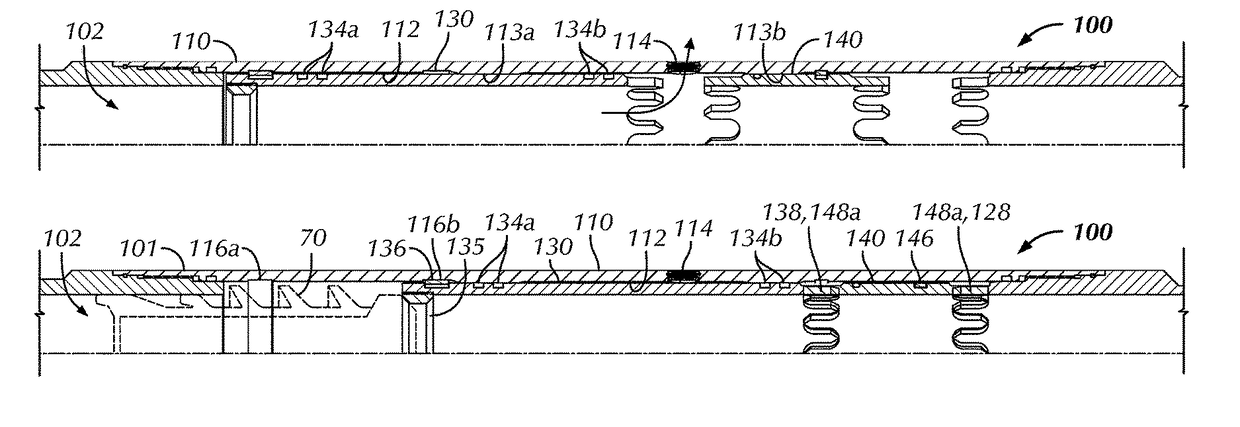
[0070]FIGS. 6A-6B illustrate a first embodiment of a hydraulically-operated stage tool 100 according to the present disclosure in cross-sectional and end-sectional views. The stage tool 100 is hydraulically-operated with plugs and is well-suited for deviated wells. As noted previously, the stage tool 100 can be used in conjunction with a packer (see e.g., FIGS. 1A-1B), although it may be used in any other configuration.

[0071]The stage tool 100 includes a housing 101 with an internal bore 102 therethrough. For assembly purposes, the housing 101 can include separate components of a tool case 110 having upper and lower subs 120a-b affixed on the case's ends 118a-b. The upper sub 120a can be a box sub for connecting to an uphole portion of a casing string (not shown), and the lower sub 120b can be a pin sub for connecting to a downhole portion of the casing string, a packer, or the like (not shown) depending on the assembly.

[0072]S...

second embodiment

B. Second Embodiment of Hydraulically-Operated Stage Tool

[0088]FIGS. 8A-8C illustrate a second embodiment of a hydraulically-actuated stage tool 100 according to the present disclosure in cross-sectional and end-sectional views. Many of the components of this second tool 100 are similar to those described above so like reference numerals are used for similar components. This second tool 100 includes a secondary closure mechanism 150 for closing the tool 100 during operations. As shown, the secondary closure mechanism 150 may be an additional component that couples to the end of the tool's housing 101 in place of the upper box sub 120a, which is instead connected to the end of the additional mechanism 150. As an alternative, the tool 100 can be integrally formed with the closure mechanism 150 integrated into the housing 101.

[0089]As best shown in the detail of FIG. 8C, the secondary closure mechanism 150 includes a chamber case 160 that threads to the end of the stage tool's case 110...

third embodiment

C. Third Embodiment of Hydraulically-Operated Stage Tool

[0098]FIGS. 10A-10C illustrate a third embodiment of a hydraulically-operated stage tool 100 according to the present disclosure in cross-sectional and end-sectional views. Many of the components of this third tool 100 are similar to those described above so like reference numerals are used for similar components. This third tool 100 also includes a secondary closure mechanism 150 for closing the tool 100 during operations. As shown, the closure mechanism 150 may be an additional component that couples to the end of the housing 101 in place of the upper box sub 120a, which is instead connected to the end of the additional mechanism 150.

[0099]Although the secondary closure mechanism 150 is shown as an additional component having a case 160, a mandrel 170, and the like, it will be appreciated that the components of the closure mechanism 150 can be incorporated directly into the other components of the tool 100. For example, as wi...


PUM


Abstract

A stage tool operable with a plug is used for cementing a tubing string in a wellbore annulus. The tool can have a housing with a closure sleeve movably disposed in the internal bore of the housing. When pressure is applied downhole to the tool, a breachable obstruction on an exit port of the tool's bore opens and allows fluid such as cement slurry to communicate to the wellbore annulus. When cementing through the open tool is finished, a plug can be deployed downhole lands on a seat in the closure sleeve, and applied fluid pressure in the tool's bore against the seated plug closes the closure sleeve relative to the housing's exit port. Rotational catches between the housing's bore and the closure sleeve prevent the closure sleeve from rotating. A hydraulic mechanism on the tool can facilitate movement of the closure sleeve in response to a fluid pressure component.

Description

BACKGROUND OF THE DISCLOSURE[0001]Cementing operations are used in wellbores to fill the annular space between casing and the formation with cement. When this is done, the cement sets the casing in the wellbore and helps isolate production zones at different depths within the wellbore from one another. Currently, the cement use during the operation can flow into the annulus from the bottom of the casing (e.g., cementing the long way) or from the top of the casing (e.g., reverse cementing).[0002]Due to weak earth formations or long strings of casing, cementing from the top or bottom of the casing may be undesirable or ineffective. For example, when circulating cement into the annulus from the bottom of the casing, problems may be encountered because a weak earth formation will not support the cement as the cement on the outside of the annulus rises. As a result, the cement may flow into the formation rather than up the casing annulus. When cementing from the top of the casing, it is ...

Claims


Application Information

Patent Timeline
Patent Type & Authority Patents(United States)
IPC IPC(8): E21B33/14E21B34/06E21B34/00
CPCE21B33/146E21B34/063E21B2034/007E21B2200/06
Inventor GIROUX, RICHARD L.
Owner WEATHERFORD TECH HLDG LLC
Why Eureka
Try Eureka