A battery module casing, a battery module and a battery

a battery module and battery module technology, applied in the direction of jackets/cases materials, cell components, nickel accumulators, etc., can solve the problems of limiting the ability of the casing to conduct heat away from the battery cell in said direction, high and voluminous batteries, and reducing so as to improve the mechanical strength of the lateral wall and improve the heat conduction and cooling of the battery module. , the effect of improving the mechanical strength

Inactive Publication Date: 2020-07-30
NILAR INT AB
View PDF0 Cites 3 Cited by
  • Summary
  • Abstract
  • Description
  • Claims
  • Application Information

AI Technical Summary

Benefits of technology

[0010]The object of the present invention is achieved by means of the initially defined battery module casing, which is characterised in that at least one of said first and second metal plates comprises at least one lateral extension that, along at least a part of a periphery of the plate to which it is associated, forms a lateral wall together with said lateral wall element. The lateral extension will thereby form a further surface from which heat may be conducted from said plate and from the battery cell. As a result thereof, heat conduction and cooling of the battery module is improved compared to a corresponding prior art design that does not comprise said lateral extensions. Provided that the at least one lateral extension of the metal plate has a higher mechanical strength than the material of the wall element together with which it forms said lateral wall, the at least one lateral extension will also contribute to an improved mechanical strength of the lateral wall. Thereby, the thickness of the lateral wall element, and the lateral wall itself, can be reduced compared to the case in which there is no lateral extension provided. Alternatively, with a maintained wall thickness, higher wall strength can be achieved, thereby allowing a higher clamping force to be applied on the battery module from outside thereof. The lateral wall element may be constituted by any suitable electrically isolating material, ceramics and porcelain included. However, according to a preferred embodiment, the lateral wall element is constituted by a polymer that has a mechanical strength that is inferior to the one of the metal of the lateral extensions of the metal plate. The lateral extensions thereby function as reinforcing members of the lateral wall.

Problems solved by technology

However, if the metal plate is covered by an electrically isolating element, typically a plastic element, the heat conductivity of that isolating element may restrict the ability of the casing to conduct heat away from the battery cell in said direction.
Some heat will also be conducted away in a lateral direction from the periphery of the metal plates, but since the metal plates normally are thin compared to their area in their extension plane, this contribution to the total heat conduction is limited.
However, this design results in a high and voluminous battery.
Furthermore, with this design it becomes difficult in reality to apply an even pressure between said conducting elements and the respective terminal plates, which is important for the functionality of this kind of batteries.

Method used


Image

  • A battery module casing, a battery module and a battery
  • A battery module casing, a battery module and a battery
  • A battery module casing, a battery module and a battery

Examples


Embodiment Construction

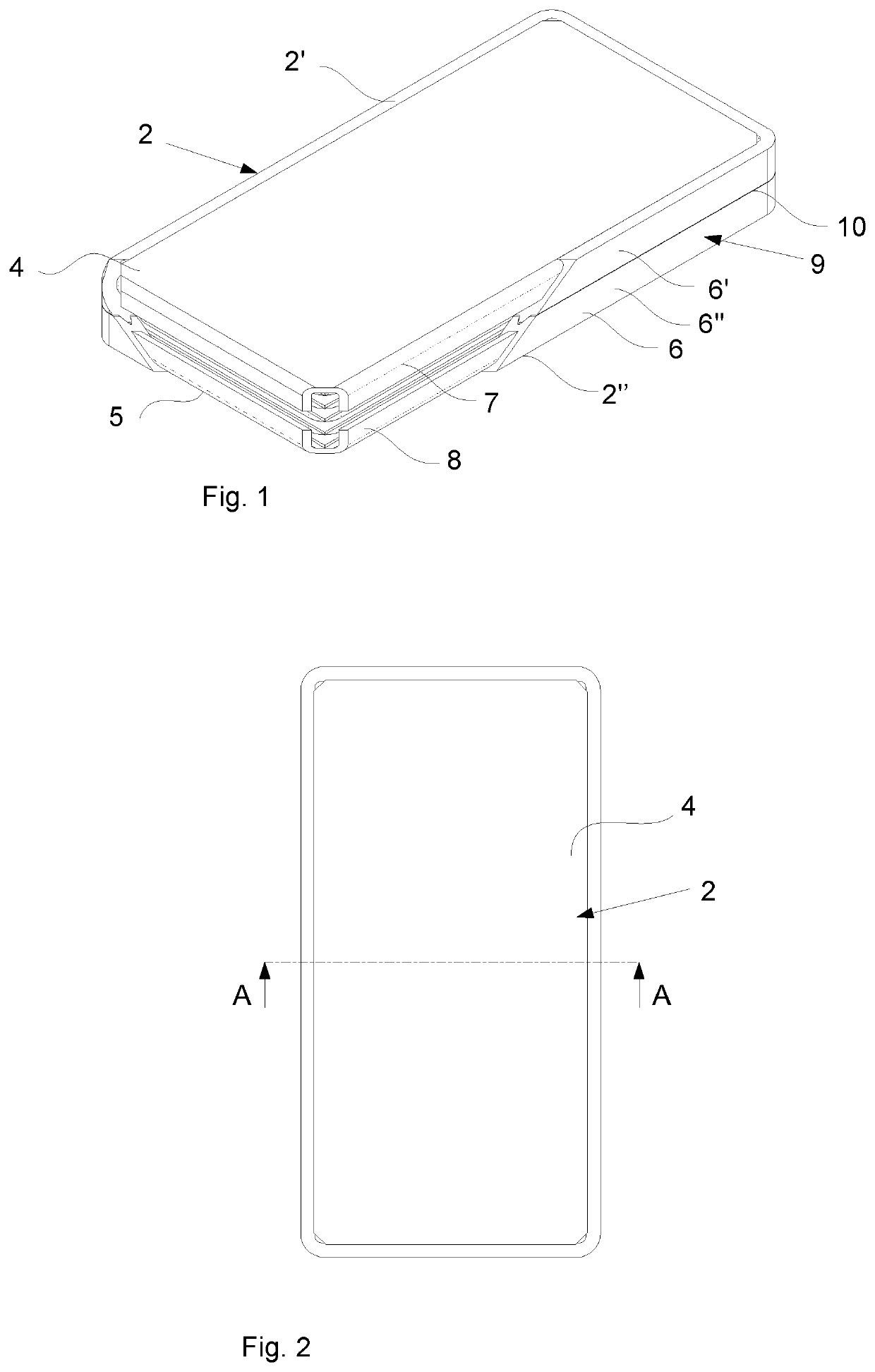
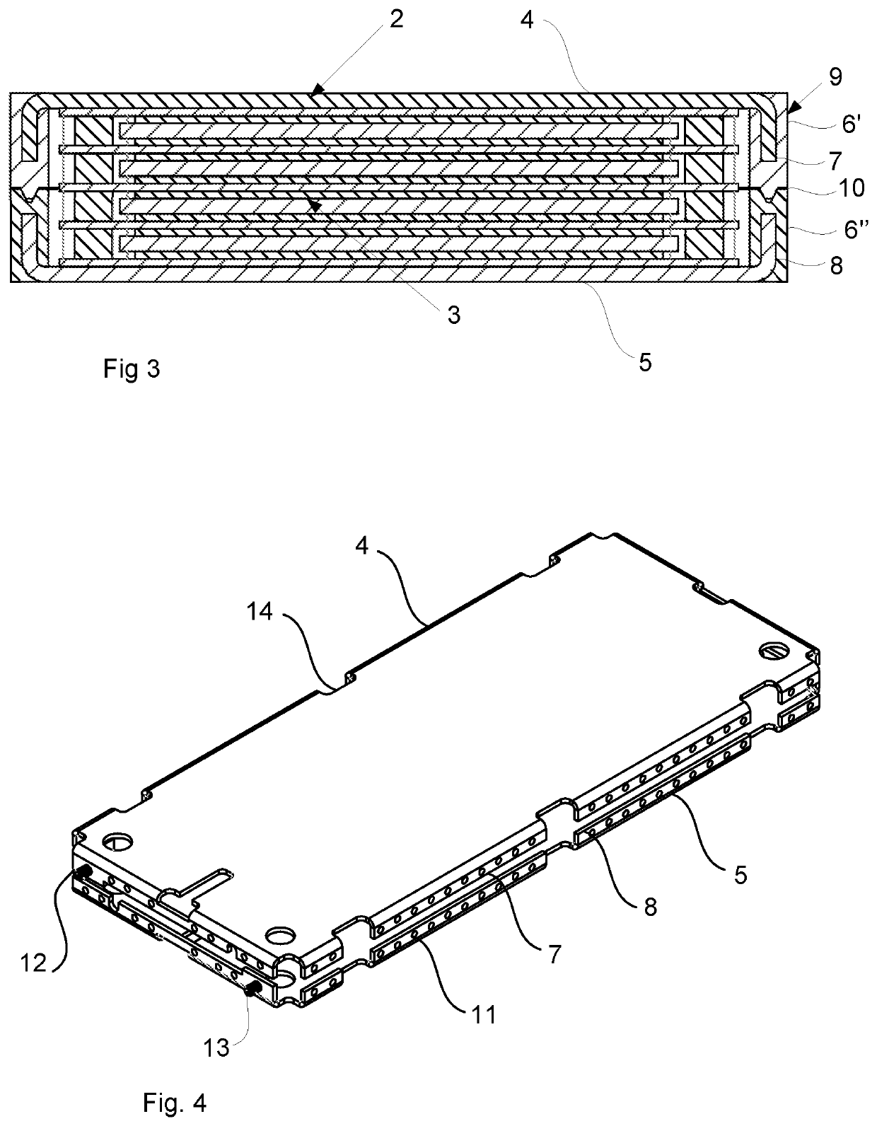
[0038]Reference is made to FIGS. 1 to 3. FIG. 1 shows a battery module casing according to an embodiment while FIGS. 2 and 3 show a battery module comprising the battery module casing shown in FIG. 1. The battery module 1 comprises the battery module casing 2 which is configured to house at least one battery cell 3, said battery module casing 2 comprising a first metal plate 4, configured to form a positive terminal of the battery module 1 and to be positioned on a first side of said at least one battery cell 3, a second metal plate 5, configured to form a negative terminal of the battery module 1 and to be positioned on an opposite second side of said at least one battery cell 3, and a lateral wall element 6 configured to extend around a lateral periphery of said at least one battery cell 3, wherein the lateral wall element 6 is located between said first metal plate 4 and said second metal plate 5, and wherein said lateral wall element 6 comprises an electrically isolating materia...


PUM

PropertyMeasurementUnit
diameteraaaaaaaaaa
diameteraaaaaaaaaa
diameteraaaaaaaaaa

Abstract

A battery module casing (2) configured to house at least one battery cell, said battery module casing (2) comprising: a first metal plate (4), configured to form a positive terminal of a battery module and to be positioned on a first side of said at least one battery cell, a second metal plate (5), configured to form a negative terminal of a battery module (1) and to be positioned on an opposite second side of said at least one battery cell, a lateral wall element (6) configured to extend around a lateral periphery of said at least one battery cell, wherein the lateral wall element (6) is located between said first metal plate (4) and said second metal plate (5), and wherein said lateral wall element (6) comprises an electrically isolating material and is sealingly attached to the first metal plate (4) and to the second metal plate (5) respectively. At least one of said first and second metal plates (4, 5) comprises at least one lateral extension (7, 8) that, along at least a part of a periphery of the plate to which it is associated, forms a lateral wall together with said lateral wall element (6).

Description

TECHNICAL FIELD[0001]The present invention relates to a battery module casing according to the preamble of claim 1.[0002]The present invention also relates to a battery module in which at least one battery cell is housed by such a battery module casing and in which the first metal plate forms a positive terminal of the battery and the second metal plate forms a negative terminal of the battery module.[0003]The invention also relates to a battery that comprises one battery module according to the present invention or a stack of at least two battery modules according to the present invention, wherein, in said stack, the second metal plate of a first of said battery modules is turned towards and located opposite to a first metal plate of a second of said battery modules, and that the outermost metal plates of said one battery module or said stack are covered by an electrically isolating element, and that there is provided a clamping element that holds the one battery module or stack of...

Claims


Application Information

Patent Timeline
Patent Type & Authority Applications(United States)
IPC IPC(8): H01M2/02H01M2/30H01M2/06H01M50/202H01M50/209H01M50/224H01M50/227H01M50/264H01M50/296H01M50/514
CPCH01M2/06H01M2/30H01M2/0285H01M2/0212H01M4/32H01M10/30Y02E60/10H01M50/103H01M50/209H01M50/202H01M50/514H01M50/224H01M50/264H01M50/296H01M50/227H01M50/531H01M10/64H01M10/65H01M50/102
Inventor NORDSTRAND, ANDREASERIKSSON, ANDERS
Owner NILAR INT AB
Why Eureka
Try Eureka