
Method of manufacturing steam turbine rotor and steam turbine rotor

a manufacturing method and steam turbine technology, applied in the direction of machines/engines, blade accessories, metal-working apparatus, etc., can solve the problems of high cost of heat-resistant alloys, insufficient high-temperature strength, and inability to meet the requirements of high-temperature strength, etc., to ensure the soundness of the steam turbine rotor 10 and the effect of excellent high-temperature strength

Inactive Publication Date: 2018-01-02
KK TOSHIBA
View PDF16 Cites 0 Cited by
  • Summary
  • Abstract
  • Description
  • Claims
  • Application Information

AI Technical Summary

Benefits of technology

[0056]According to the configuration or structure described above, the present embodiment provides the following advantageous effects (1) to (8).
[0057](1) The first electrode 17 is produced by melting a Ni-based superalloy, the ESR ingot 21 is obtained by subjecting the first electrode 17 and the second electrode 18 to the ESR, and the steam turbine rotor 10 is then produced after going through stages of a rotor forging and a rotor blank in sequence, so that the present embodiment can produce the steam turbine rotor by overcoming limitations in the manufacture of the Ni-based superalloy such as inability to produce a large-size parts.
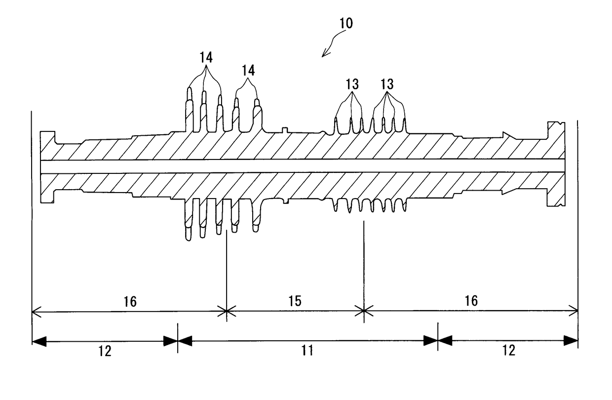
[0058](2) Since the ultra-high temperature side portion 15 of the steam turbine rotor 10 is made of an Ni-based superalloy with excellent high-temperature strength, the present embodiment can ensure soundness of the steam turbine rotor 10 even against ultra-high temperature steam in excess of 600° C.
[0059](3) Although the first electrode 17 for the ESR is made of an expensive Ni-based superalloy, since the second electrode 18 is made of ferritic heat resistant steel, the present embodiment can produce the steam turbine rotor 10 at low cost after a stage of the ESR ingot 21 produced by using the first electrode 17 and the second electrode 18.
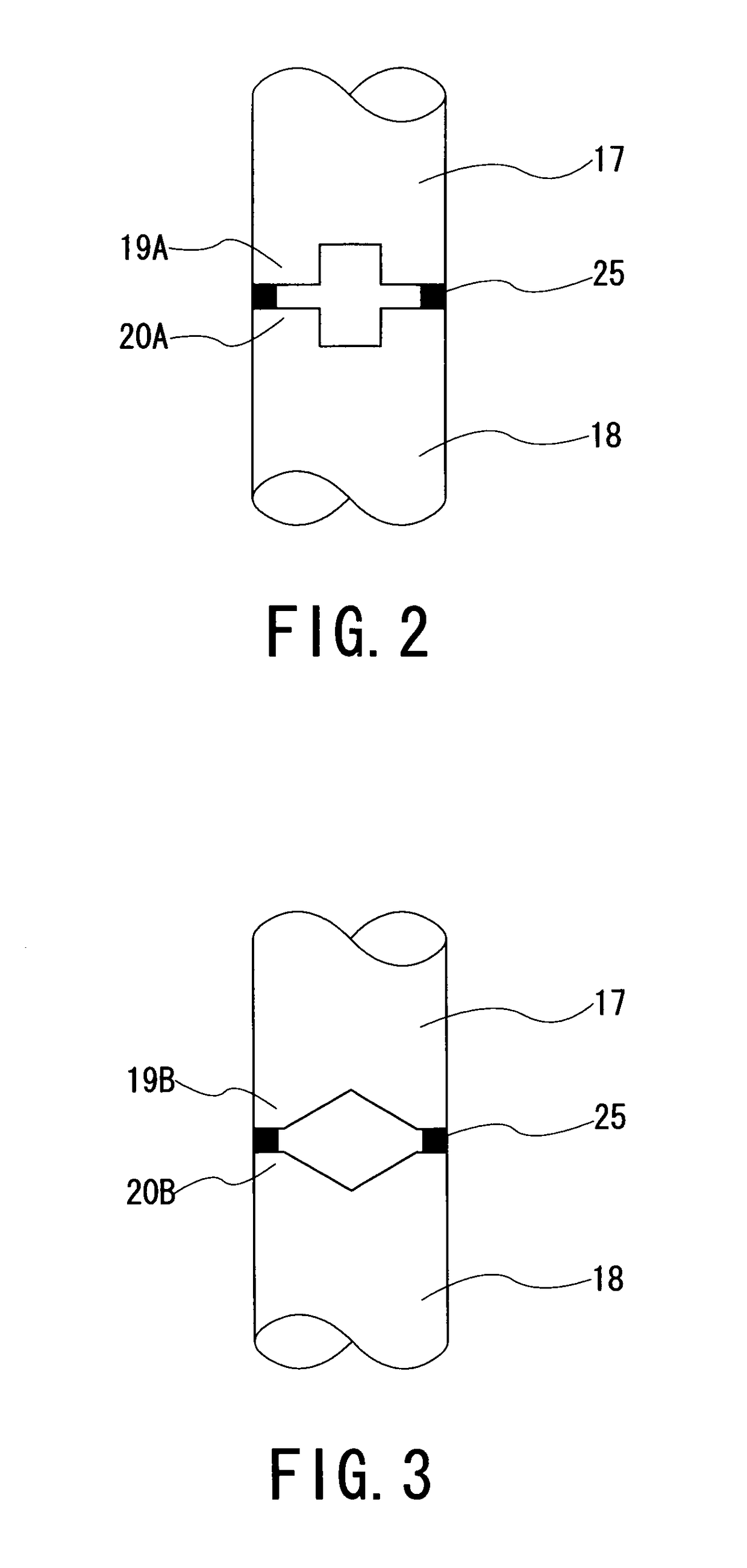
[0060](4) The joint (19A, 19B, 19C, or 19D) of the first electrode 17 and the joint (20A, 20B, 20C, or 20D) of the second electrode 18 are configured to be smaller in cross sectional area than the other parts of the first electrode 17 and the second electrode 18, respectively. Therefore, in the ESR using the first electrode 17 and the second electrode 18, the present embodiment can decrease meltage of the joint (19A, 19B, 19C, or 19D) and the joint (20A, 20B, 20C, or 20D), resulting in a shallow melt pool, thereby allowing the melt pool to be flattened and solidification speed to be increased. This allows the transition width W of the composition transition region 24 in the ESR ingot 21 to be reduced, making it possible to increase the quality of the steam turbine rotor 10 manufactured by passing through a stage of the ESR ingot 21 and improve the reliability of the long-term operation of the steam turbine rotor 10.
[0061](5) Since the joint (19A, 19B, 19C, or 19D) of the first electrode 17 and the joint (20A, 20B, 20C, or 20D) of the second electrode 18 are configured to be smaller in cross sectional area than the other parts of the first electrode 17 and the second electrode 18, respectively, the first electrode 17 and the second electrode 18 can be shortened in comparison with a case of both the electrodes being hollow. This makes it possible to downsize the ESR furnace and the like in which the first electrode 17 and the second electrode 18 are mounted.

Problems solved by technology

With such increases in the temperature, the steam turbine rotor applied tends to switch to heat-resistant alloys such as Ni-based superalloys having better high-temperature strength than ferritic heat resistant steels (such as 1% Cr—Mo—V steel or 12% Cr steel), which have insufficient high-temperature strength.
However, with such heat-resistant alloys, due to limitations of melting facilities, production on the order of ten-odd tons is a limit in terms of product weight.
Further, heat-resistant alloys are higher in cost than ferritic heat resistant steels.
The welded joint has many problems to be solved from the viewpoint of rotor design and long-term reliability, including weld defects, welding deformation, and welding residual stress which may occur in the joint.
On the other hand, the bolted joint requires a larger rotor wheel interval in the joint than an optimum design interval, resulting in performance degradation of the steam turbine rotor.
Further, the bolted joint is not applicable to a drum rotor structure though applicable to a wheel structure.

Method used


Image

  • Method of manufacturing steam turbine rotor and steam turbine rotor
  • Method of manufacturing steam turbine rotor and steam turbine rotor
  • Method of manufacturing steam turbine rotor and steam turbine rotor

Examples


second embodiment

(2) Second Embodiment

[0065]In the second embodiment, components similar to those in the first embodiment are denoted by the same reference numerals as the corresponding components, and description thereof will be simplified or omitted.

[0066]The present embodiment differs from the first embodiment in that: the ultra-high temperature side portion 15 and the high temperature side portion 16 of the steam turbine rotor 10 are made of the same heat resistant alloy, e.g., a Ni-based superalloy, and thus both the first electrode 17 and the second electrode 18 used for ESR manufacturing of the steam turbine rotor 10 have a chemical composition corresponding to the chemical composition of the Ni-based superalloy.

[0067]In this case, both the ultra-high temperature side portion 22 and the high temperature side portion 23 of the ESR ingot 21 produced by the ESR process by using the first electrode 17 and the second electrode 18 are made of the Ni-based superalloy, and thus, there is no compositi...


PUM

PropertyMeasurementUnit
steam temperatureaaaaaaaaaa
temperatureaaaaaaaaaa

Abstract

A method of manufacturing a steam turbine rotor which includes an ultra-high temperature side portion in which ultra-high temperature steam flows and a high temperature side portion in which high temperature steam flows, the manufacturing method including the steps of: preparing a first electrode having a chemical composition corresponding to a chemical composition of a heat resistant alloy making up the ultra-high temperature side portion and a second electrode having a chemical composition corresponding to a chemical composition of the high temperature side portion; tentatively joining together joints of the electrodes, with the joints of the electrodes made smaller in cross sectional area than other electrode portions; subjecting the tentatively joined first and second electrodes to an ESR process to obtain an ESR ingot and forging the ingot into a shape of a rotor to obtain a rotor forging; and heat-treating the rotor forging to obtain a rotor blank and manufacturing the steam turbine rotor from the rotor blank.

Description

TECHNICAL FIELD[0001]The present invention relates to a method of manufacturing a steam turbine and a steam turbine rotor, and particularly, to a method of manufacturing a steam turbine rotor by utilizing electro-slag remelting (hereinafter referred to as ESR) process and to a steam turbine rotor manufactured by the steam turbine rotor manufacturing method.BACKGROUND[0002]Generally, a steam turbine rotor is manufactured in a manner of melting and refining raw materials so as to finally obtain a predetermined chemical composition, which are then cast and solidified in a mold, forging a solidified ingot into a shape of the rotor to obtain a rotor forging product, heat-treating the rotor forging product to obtain a rotor blank, machining the rotor blank, and implanting rotor blades in the rotor blank.[0003]Alternatively, a steam turbine rotor may sometimes be manufactured in a manner of melting and refining raw materials as described above, remelting the resulting ingot in an ESR furna...

Claims


Application Information

Patent Timeline
Patent Type & Authority Patents(United States)
IPC IPC(8): F01D5/06
CPCF01D5/06Y10T29/49316F05D2220/31
Inventor YAMADA, MASAYUKIINUKAI, TAKAOIMAI, KIYOSHIMIYASHITA, SHIGEKAZUNEMOTO, KUNIYOSHITAKAKU, REKI
Owner KK TOSHIBA
Learn More