Welded structure member and manufacturing method thereof

a technology of welded structure and manufacturing method, which is applied in the field can solve the problems of difficulty in sufficiently achieve the effects of improving the fatigue strength of welded structure members, simple configuration, and reducing the restriction on manufacturing

Active Publication Date: 2020-06-23
NIPPON STEEL CORP
View PDF18 Cites 0 Cited by
  • Summary
  • Abstract
  • Description
  • Claims
  • Application Information

AI Technical Summary

Benefits of technology

[0030]According to the present invention, it is possible to improve a fatigue strength of the welded structure member by a simple configuration, that is, by forming the linear weld overlay section on the second surface (a rear surface) of the base metal member. In this case, a restriction on the manufacturing decreases, and it is possible to easily improve the fatigue strength of the welded structure member. Specifically, for example, even in a case where a plate-like section of the joined metal member is welded to a plate-like section of the base metal member by being greatly inclined, it is not necessary to form the weld overlay section between both of the plate-like sections, and thus, the restriction on the manufacturing does not increase. Accordingly, it is possible to easily manufacture the welded structure member of which the fatigue strength is improved.

Problems solved by technology

However, in the related art, it is known that even in a case of using the high-strength steel sheet, it is difficult to sufficiently improve the fatigue strength of the welded structure member.

Method used


Image

  • Welded structure member and manufacturing method thereof
  • Welded structure member and manufacturing method thereof
  • Welded structure member and manufacturing method thereof

Examples


first embodiment

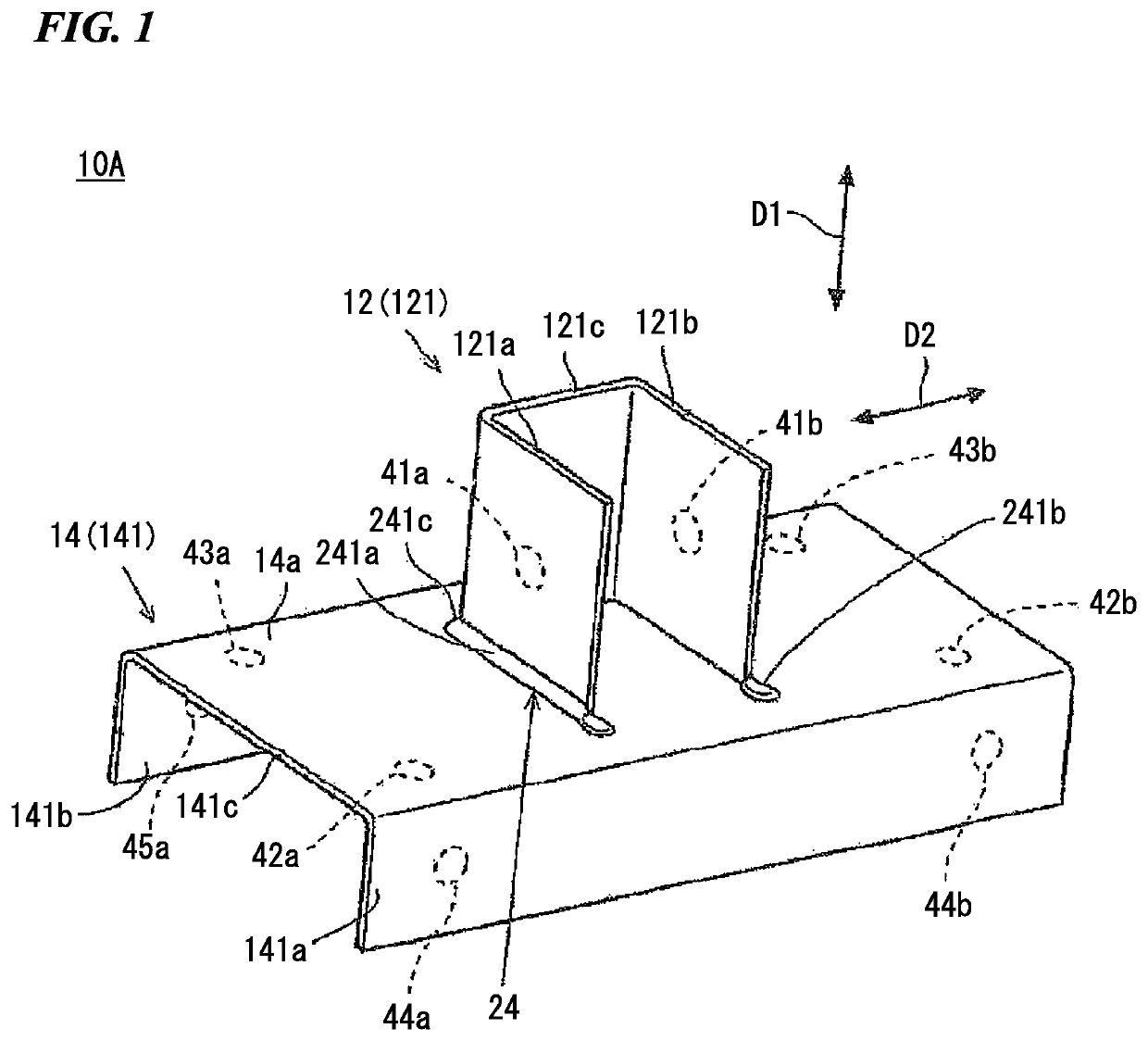
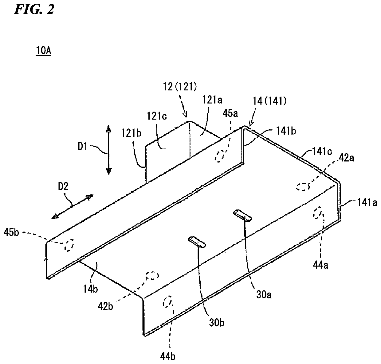
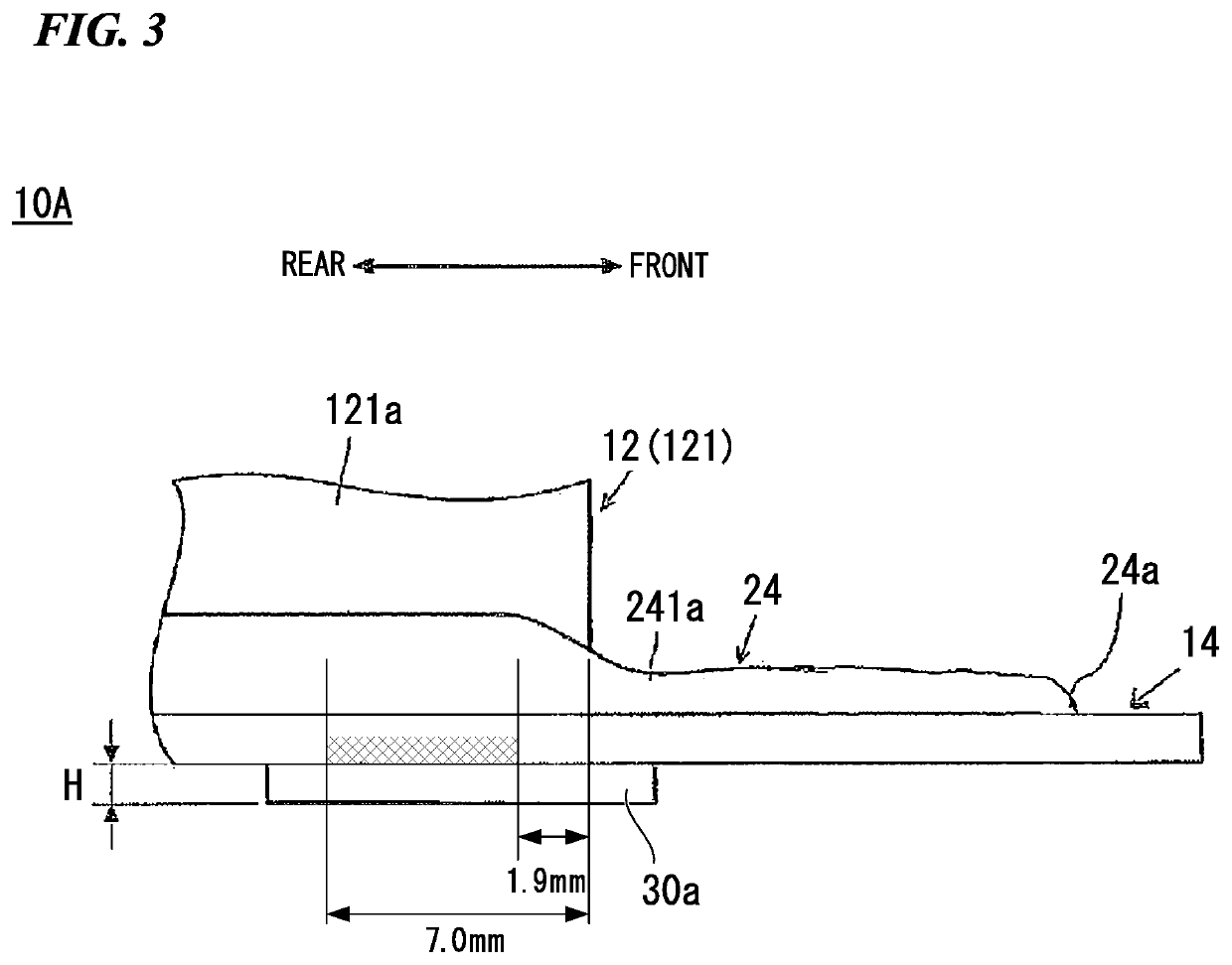
[0089]FIG. 1 is a perspective view illustrating a welded structure member 10A according to a first embodiment of the present invention, FIG. 2 is a perspective view of the welded structure member 10A seen from a lower side, FIG. 3 is a side view illustrating a part of the welded structure member 10A, and FIG. 4 is a projection view of an abutting surface 32, a weld bead 24, and weld overlay sections 30a and 30b of the welded structure member 10A. Furthermore, in FIG. 1 and FIG. 2, dotted circles 41a, 41b, 42a, 42b, 43a, 43b, 44a, 44b, 45a, and 45b illustrate positions of holes formed on an analysis model in a simulation described below. The details thereof will be described below.

[0090]As illustrated in FIG. 1, the welded structure member 10A according to this embodiment includes a joined metal member 12 which extends in a first direction D1, a base metal member 14 which extends in a second direction D2 intersecting with the first direction D1 and to which an end surface of the join...

second embodiment

[0132]Next, a welded structure member 10B according to a second embodiment of the present invention will be described. The welded structure member 10B according to the second embodiment has the same configuration as that of the welded structure member 10A according to the first embodiment except for the position where the weld overlay sections 30a and 30b are formed, and thus, the same reference numerals are applied to the same constituents, and the description thereof will be omitted.

[0133]In FIG. 6 to FIG. 9, the welded structure member 10B according to the second embodiment is illustrated. More specifically, FIG. 6 is a perspective view of the welded structure member 10B seen from an upper side, FIG. 7 is a perspective view of the welded structure member 10B seen from a lower side, FIG. 8 is a side view illustrating a part of the welded structure member 10B, and FIG. 9 is a projection view of the abutting surface 32, the weld bead 24, and the weld overlay sections 30a and 30b of ...


PUM

PropertyMeasurementUnit
lengthaaaaaaaaaa
lengthaaaaaaaaaa
heightaaaaaaaaaa

Abstract

This welded structure member includes a base metal member including a first surface and a second surface; a joined metal member including an abutting surface of which an end surface abuts onto the first surface; a weld bead which is formed on the first surface; and a weld overlay section which is formed on the second surface of the base metal member, in which the weld bead includes a weld bead end section in a position which is separated to the front of the abutting end section.

Description

TECHNICAL FIELD OF THE INVENTION[0001]The present invention relates to a welded structure member and a manufacturing method thereof.[0002]Priority is claimed on Japanese Patent Application No. 2014-204583, filed on Oct. 3, 2014, and Japanese Patent Application No. 2015-158817, filed on Aug. 11, 2015, the contents of which are incorporated herein by reference.RELATED ART[0003]Recently, in order to improve a fuel efficiency of a vehicle, weight saving of a vehicle body has progressed. Then, in order to realize the weight saving of the vehicle body, a welded structure member in which high-strength steel sheets are welded to each other is used as a vehicle body material.[0004]The welded structure member which is used as the vehicle body material is required to have an excellent fatigue strength. However, in the related art, it is known that even in a case of using the high-strength steel sheet, it is difficult to sufficiently improve the fatigue strength of the welded structure member. ...

Claims


Application Information

Patent Timeline
Patent Type & Authority Patents(United States)
IPC IPC(8): B23K9/025B62D27/02F16B5/08B23K31/00B23K9/02B62D21/11
CPCB23K31/003F16B5/08B62D27/02B23K9/025B62D21/11B23K9/02B23K31/02B23K2101/006B23K9/028B23K31/00B23K33/00
Inventor OGAWA, MASAHIROOAMI, SHOKOKODAMA, SHINJI
Owner NIPPON STEEL CORP
Why Eureka
Try Eureka