Devices, systems, and methods for reshaping a heart valve annulus

a technology of heart valve and annulus, which is applied in the field of devices, systems, and methods for reshaping the heart valve annulus, can solve the problems of leaflets that flail, valve malfunction, and chordae tendinea (the chords) being stretched, and achieves the effects of less invasiveness, simple structure, and less invasiveness

Active Publication Date: 2018-01-09
MVRX INC +1
View PDF98 Cites 27 Cited by
  • Summary
  • Abstract
  • Description
  • Claims
  • Application Information

AI Technical Summary

Benefits of technology

[0022]The invention provides devices, systems and methods that reshape a valve annulus. The devices, systems, and methods include an implant that is sized and configured to rest near or within the leaflet commissures of a heart valve annulus. In use, the implant contacts and outwardly displaces tissue to reshape the heart valve annulus. The implant, in use, may restore to the heart valve annulus and leaflets a more effective anatomic shape and tension. The more normal anatomic shape and tension are conducive to coaptation of the leaflets during systole, which, in turn, reduces regurgitation. The implant restores function to the valve, without surgically cinching, resecting, and / or fixing in position large portions of a dilated annulus, or without the surgical fixation of ring-like structures.

Problems solved by technology

Valve malfunction can result from the chordae tendinea (the chords) becoming stretched, and in some cases tearing.
When a chord tears, the result is a leaflet that flails.
Also, a normally structured valve may not function properly because of an enlargement of or shape change in the valve annulus.
This condition is referred to as a dilation of the annulus and generally results from heart muscle failure.
In addition, the valve may be defective at birth or because of an acquired disease.
As a result, an undesired back flow of blood from the left ventricle into the left atrium can occur.
During subsequent diastole (when the heart relaxes), this “extra” blood returns to the left ventricle, creating a volume overload, i.e., too much blood in the left ventricle.
This means that: (1) the heart must pump harder to move the extra blood; (2) too little blood may move from the heart to the rest of the body; and (3) over time, the left ventricle may begin to stretch and enlarge to accommodate the larger volume of blood, and the left ventricle may become weaker.
Although mild cases of mitral valve regurgitation result in few problems, more severe and chronic cases eventually weaken the heart and can result in heart failure.

Method used


Image

  • Devices, systems, and methods for reshaping a heart valve annulus
  • Devices, systems, and methods for reshaping a heart valve annulus
  • Devices, systems, and methods for reshaping a heart valve annulus

Examples


Embodiment Construction

[0076]Although the disclosure hereof is detailed and exact to enable those skilled in the art to practice the invention, the physical embodiments herein disclosed merely exemplify the invention, which may be embodied in other specific structure. While the preferred embodiment has been described, the details may be changed without departing from the invention, which is defined by the claims.

I. Implants for Reshaping a Heart Valve Annulus

[0077]A. Overview

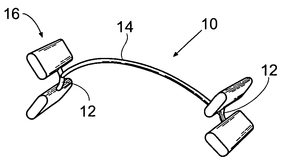
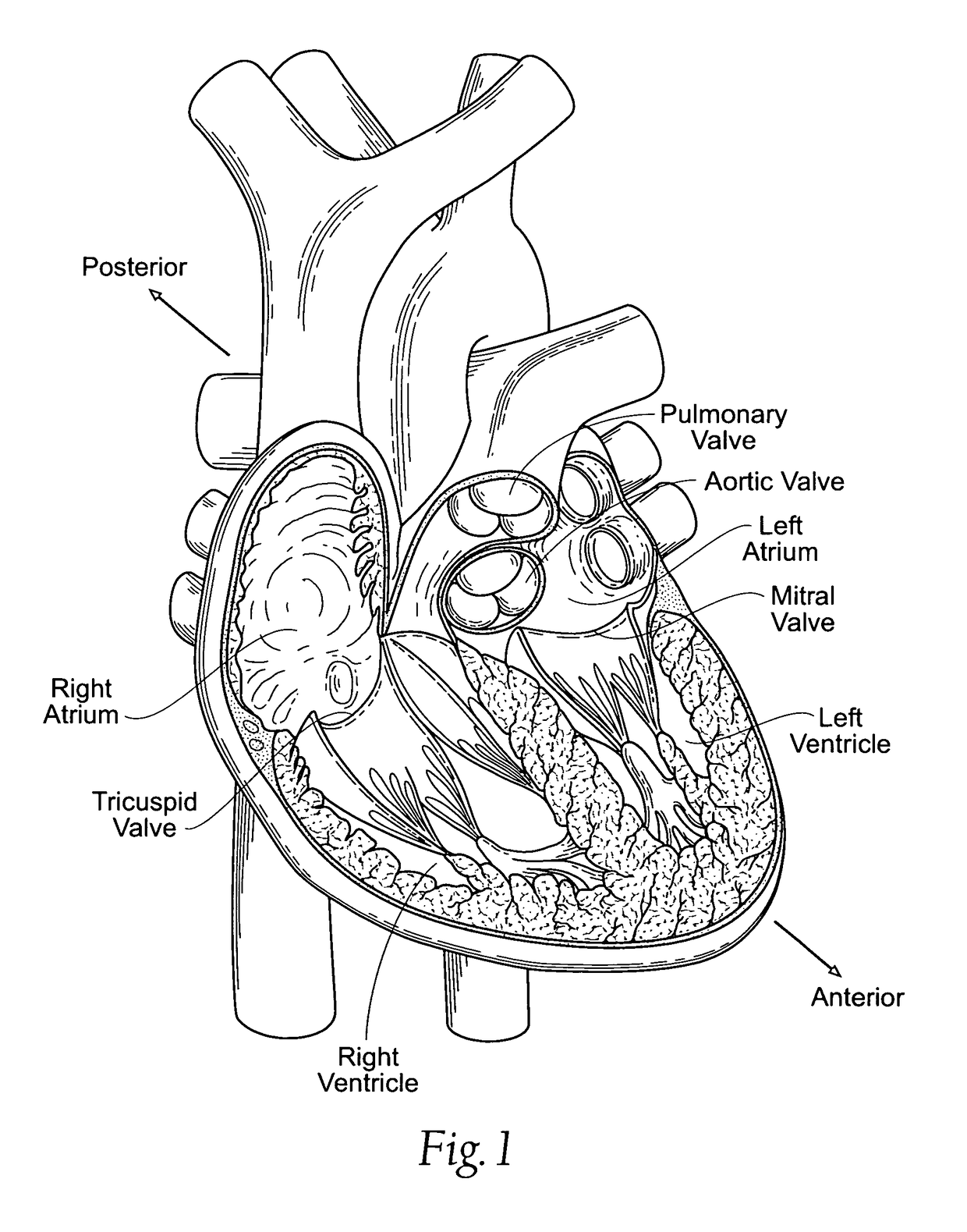
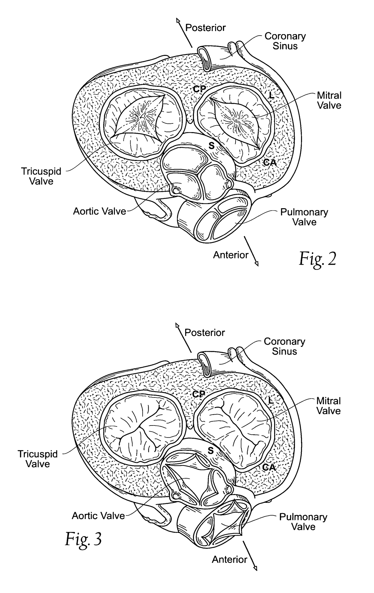
[0078]FIGS. 7A and 8 show an implant 10 sized and configured to rest within or near a heart valve annulus. In use, the implant is shown in a mitral valve, and, in this arrangement, extends along the major (i.e., longest) axis above and / or along the valve annulus. The implant 10 is sized and shaped so that, in use, it applies a mechanical force along the major axis. The mechanical force serves to outwardly displace tissue (i.e., to displace tissue away from the center of the annulus) to reshape the annulus. In the illustrated embodimen...


PUM


Abstract

Devices, systems, and methods employ an implant that is sized and configured to attach to the annulus of a dysfunctional heart valve annulus. In use, the implant extends across the major axis of the annulus above and / or along the valve annulus. The implant reshapes the major axis dimension and / or other surrounding anatomic structures. The implant restores to the heart valve annulus and leaflets a more functional anatomic shape and tension. The more functional anatomic shape and tension are conducive to coaptation of the leaflets during systole, which, in turn, reduces regurgitation. The implant improves function to the valve, without surgically cinching, resecting, and / or fixing in position large portions of a dilated annulus, or without the surgical fixation of ring-like structures.

Description

RELATED APPLICATIONS[0001]This application is a continuation of U.S. patent application Ser. No. 10 / 677,104, filed Oct. 1, 2003, and claims the benefit of U.S. Provisional Application Ser. No. 60 / 429,444, filed Nov. 26, 2002, and entitled “Heart Valve Remodeling Devices”.FIELD OF THE INVENTION[0002]The invention is directed to devices, systems, and methods for improving the function of a heart valve, e.g., in the treatment of mitral valve regurgitation.BACKGROUND OF THE INVENTIONI. The Anatomy of a Healthy Heart[0003]The heart (see FIG. 1) is slightly larger than a clenched fist. It is a double (left and right side), self-adjusting muscular pump, the parts of which work in unison to propel blood to all parts of the body. The right side of the heart receives poorly oxygenated (“venous”) blood from the body from the superior vena cava and inferior vena cava and pumps it through the pulmonary artery to the lungs for oxygenation. The left side receives well-oxygenation (“arterial”) bloo...

Claims


Application Information

Patent Timeline
Patent Type & Authority Patents(United States)
IPC IPC(8): A61F2/24A61B17/00A61F
CPCA61F2/2418A61F2/2445A61F2/2466A61F2/2454A61F2220/0016A61B2017/00243A61B17/22012A61B18/1492A61B90/00A61B90/50A61B2017/00247A61B2017/22097A61B2017/320052A61B2018/00392A61F2/2412Y10S623/904
Inventor MACHOLD, TIMOTHY R.RAHDERT, DAVID A.MACOVIAK, JOHN A.CHANG, ROBERT T.SOSS, RICK A.
Owner MVRX INC
Why Eureka
Try Eureka