Modular power supply and method for manufacturing the same

a power supply and module technology, applied in the direction of transformer/inductance magnetic core, electrical apparatus construction details, printed circuit non-printed electric components association, etc., can solve the problems of poor heat dissipation, large thermal resistance between power components and heat sinks, and complex structure of heat sinks, etc., to achieve excellent heat dissipation structure

Active Publication Date: 2018-01-09
DELTA ELECTRONICS (SHANGHAI) CO LTD
View PDF7 Cites 15 Cited by
  • Summary
  • Abstract
  • Description
  • Claims
  • Application Information

AI Technical Summary

Benefits of technology

[0013]It is an object of the present invention to overcome defects in the prior art by providing a modular power supply with an excellent heat dissipation structure and a method for manufacturing the same.
[0032]S102, assembling the magnetic core in the mounting grooves of the printed circuit board by using the planar carrier as a baffle to make the lower surface of the magnetic core and the lower surface of the printed circuit board be in a same plane, making the lower surface of the magnetic core be engaged with the upper surface of the heat sink, and thus minimizing thermal resistance between the magnetic element and the heat sink.
[0035]S102, assembling the magnetic core in the mounting grooves of the printed circuit board by using the planar carrier as a baffle to make the lower surface of the magnetic core and the lower surface of the printed circuit board be in a same plane, making the lower surface of the magnetic core be engaged with the upper surface of the heat sink, and thus minimizing thermal resistance between the magnetic element and the heat sink;
[0039]S102, assembling the lower portion of the magnetic core into the mounting grooves of the printed circuit board by using the planar carrier as a baffle to make the lower surface of the magnetic core and the lower surface of the printed circuit board be in a same plane, making the lower surface of the magnetic core be engaged with the upper surface of the heat sink, and thus minimizing thermal resistance between the magnetic element and the heat sink;
[0044]The modular power supply has excellent heat dissipation effect, and the production and assembly process thereof is simplified, so that the production efficiency is improved and the quality is guaranteed.

Problems solved by technology

Thermal resistance between the power components and the heat sink is large, and the heat dissipation is poor.
The heat sink is complicated in structure.
It is difficult to deal with the isolation between the modular power supply and the heat sink.
1. Thermal resistance between hot sources of semiconductor devices in the power components 100 and the top of the case is very large (>15° C. / W).
2. Since power components 100 are of different heights, there are many steps in the heat sink 300. As a result, the heat sink 300 is complex in structure, and it is difficult to deal with the isolation between the heat sink 300 and a module. Generally, an insulating layer is required for each platform, and steps are required to overlap with each other. However, requirements regarding insulation probably can not be met in this case.
3. Generally, the number of steps in the heat sink 300 is controlled to 2 or 3. In this case, the power components 100 from which heat can be dissipated directly via the heat sink 300 are limited in number.
4. Due to the tolerance in height of the power components 100, it is required to fill a gap between the heat sink 300 and the power components 100 with the heat-conducting glue 400. Thermal resistance will be increased to a certain extent. For example, heat-conducting glue with a thickness of 0.3 mm has thermal resistance of about 5.5° C. / W.
5. Since there is a distance between the heat sink 300 and the printed circuit board 200, heat from the printed circuit board 200 can not be dissipated directly via the heat sink 300.
6. Generally, power components 100 are disposed on both surfaces of the printed circuit board 200. In this case, there is no path for the heat from power components 100 on one of the surface to be dissipated directly to the heat sink 300.

Method used


Image

  • Modular power supply and method for manufacturing the same
  • Modular power supply and method for manufacturing the same
  • Modular power supply and method for manufacturing the same

Examples


Embodiment Construction

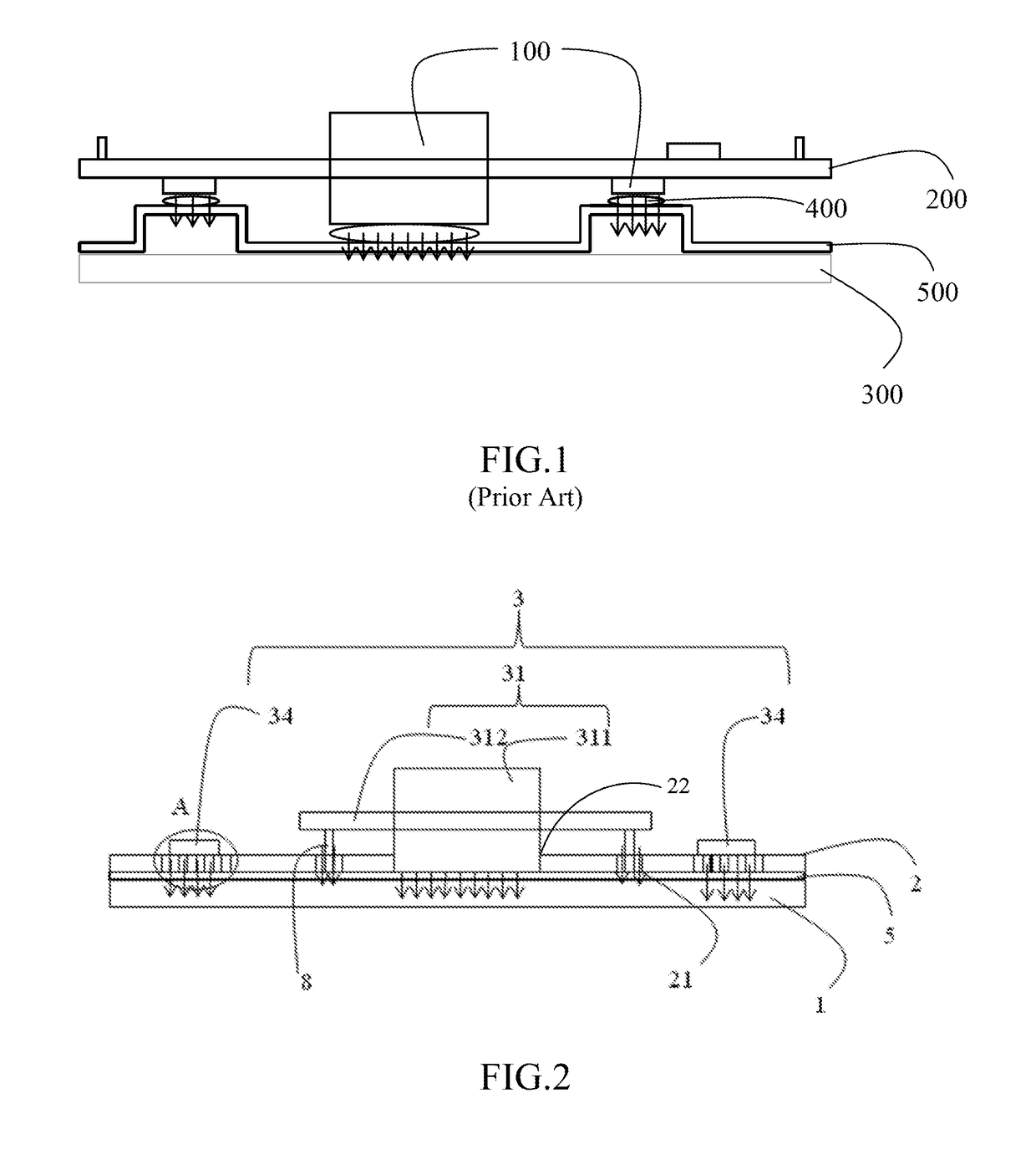
[0053]The structure and operation of a modular power supply according to the present invention will be described in details hereinafter by referring to the accompanying drawings.

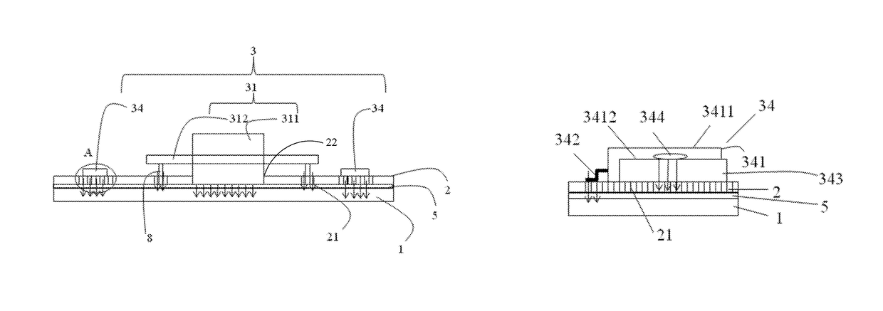
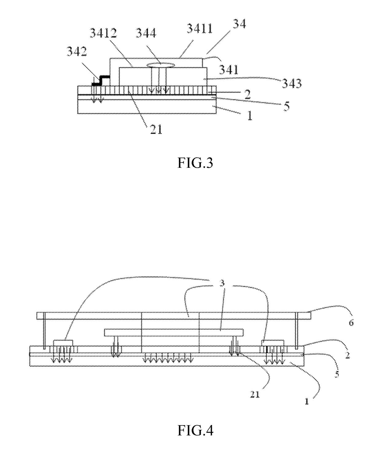
[0054]Reference is made to FIG. 2 and FIG. 3. FIG. 2 is a structural view illustrating a modular power supply according to an embodiment of the present invention, and FIG. 3 is an enlarged diagram of a portion A in FIG. 2. The modular power supply of the present invention comprises a printed circuit board 2, power components 3, and a heat sink 1. The power components 3 are mounted on the printed circuit board 2. An upper surface of the heat sink 1 is planar. The heat sink 1 for example can be a rectangular plate. The power components 3 are mounted on the printed circuit board 2 and disposed at a side opposite to the heat sink 1. A lower surface of the printed circuit board 2, which is also planar, is engaged with the upper surface of the heat sink 1, with an insulating layer 5 being disposed between the uppe...


PUM

PropertyMeasurementUnit
thicknessaaaaaaaaaa
magneticaaaaaaaaaa
thermal resistanceaaaaaaaaaa

Abstract

A modular power supply and a method for manufacturing the same are disclosed. The modular power supply comprises a printed circuit board, power components, and a heat sink. The power components are mounted on the printed circuit board and disposed at a side opposite to the heat sink, a lower surface of the printed circuit board is engaged with an upper surface of the heat sink which is planar, and an insulating layer is disposed between the upper surface of the heat sink and the lower surface of the printed circuit board. A method for manufacturing the modular power supply is also disclosed. The modular power supply has excellent heat dissipation effect, and the production and assembly process thereof is simplified, so that the production efficiency is improved and the quality is guaranteed.

Description

CROSS-REFERENCE TO RELATED APPLICATIONS[0001]This non-provisional application claims priority under 35 U.S.C. §119(a) on Patent Application No. 201520549423.9 filed in P.R. China on Jul. 27, 2015, the entire contents of which are hereby incorporated by reference.[0002]Some references, if any, which may include patents, patent applications and various publications, may be cited and discussed in the description of this invention. The citation and / or discussion of such references, if any, is provided merely to clarify the description of the present invention and is not an admission that any such reference is “prior art” to the invention described herein. All references listed, cited and / or discussed in this specification are incorporated herein by reference in their entireties and to the same extent as if each reference was individually incorporated by reference.FIELD OF THE INVENTION[0003]The present invention relates to a modular power supply and a method for manufacturing the same, ...

Claims


Application Information

Patent Timeline
Patent Type & Authority Patents(United States)
IPC IPC(8): H05K7/20H05K1/18H05K1/02H05K3/30H01F27/24
CPCH05K1/0203H01F27/24H05K7/209H05K1/181H05K3/30H05K1/0204H01F27/22H01F27/2804H01F27/292
Inventor CHEN, SHIJIEDENG, YANWEI, ZHIHUI
Owner DELTA ELECTRONICS (SHANGHAI) CO LTD
Why Eureka
Try Eureka