Stereo X-ray tube based suppression of outside body high contrast objects

a technology of x-ray tube and object, applied in the field of image processing apparatus, can solve the problems of disturbing visual content, spurious image content, etc., and achieve the effect of saving cpu tim

Active Publication Date: 2018-01-16
KONINKLJIJKE PHILIPS NV
View PDF8 Cites 0 Cited by
  • Summary
  • Abstract
  • Description
  • Claims
  • Application Information

AI Technical Summary

Benefits of technology

[0012]The apparatus proposed herein uses the stereo or binocular disparity of image content to estimate the depth of the respective structure. This allows distinguishing between structures inside and outside the body. Image content originating from objects outside the body is removed from the image. The so processed image then affords when viewed a substantially un-obscured clear view on the clinically interesting anatomical structures.
[0020]According to one embodiment, the object footprint detector is configured to by-pass / leapfrog the image depth resolver if, based on the used criteria, the object is a priori determined to be external. This affords saving CPU time in cases where object recognition allows unambiguously to conclude that the relevant shape originates from an external object.

Problems solved by technology

In interventional imaging settings, cables, electronic devices and sundry equipment are often located outside a patient's body and frequently create spurious image content in intra-interventional imaging.
This image content originating from instrumentation or other devices outside the body can be visually disturbing, in particular in time-critical settings.

Method used


Image

  • Stereo X-ray tube based suppression of outside body high contrast objects
  • Stereo X-ray tube based suppression of outside body high contrast objects
  • Stereo X-ray tube based suppression of outside body high contrast objects

Examples


Embodiment Construction

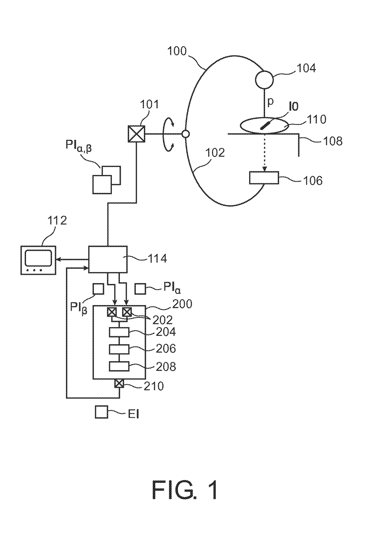
[0032]With reference to FIG. 1, there is shown an x-ray imager 100 of the C-arm type. X-ray imager 100 is used to acquire at least two projection images PIα, PIβ of a patient 110 who is supported by an examination table 108.

[0033]Imager 100 comprises a rigid C-arm structure 102 journaled on a bearing. Journaling allows rotation of C-arm 102 around a first axis passing through journaling.

[0034]C-arm structure 102 can thus be positioned at various rotation angles α around patient 110.

[0035]C-arm 102 carries at one of its ends an x-ray source 104 and at the other end a detector 106 in opposed spatial relationship to x-ray source 104. Detector 106 includes an array of detector cells (not shown).

[0036]X-rays are emitted from x-ray source 104. The X-rays pass through patient's body 110 and are then detected at detector 120. The X-rays are formed from as an X-ray pencil beam p.

[0037]Each x-ray beam p is attenuated as it passes through the patient and impact on same. It is this attenuated x...


PUM


Abstract

A double focal spot X-ray tube is used to acquire a set of two images PIα, PIβ for a given gantry position from slightly different view positions. The stereo or binocular disparity (BD) of imaged structures is used to estimate the object depth in view direction, which in turn is used to discriminate between objects inside IO and outside EO the body. Respective structures are virtually removed from the images PIα, PIβ.

Description

CROSS-REFERENCE TO PRIOR APPLICATIONS[0001]This application is the U.S. National Phase application under 35 U.S.C. §371 of International Application Serial No. PCT / IB2013 / 051699, filed on Mar. 4, 2013, which claims the benefit of U.S. Application Ser. No. 61 / 607,040, filed on Mar. 6, 2012. These applications are hereby incorporated by reference herein.FIELD OF THE INVENTION[0002]The present invention relates to an image processing apparatus, to a method of image processing, to an imaging system, to a computer program element, and to a computer readable medium.BACKGROUND OF THE INVENTION[0003]In interventional imaging settings, cables, electronic devices and sundry equipment are often located outside a patient's body and frequently create spurious image content in intra-interventional imaging. This image content originating from instrumentation or other devices outside the body can be visually disturbing, in particular in time-critical settings.SUMMARY OF THE INVENTION[0004]There may...

Claims


Application Information

Patent Timeline
Patent Type & Authority Patents(United States)
IPC IPC(8): A61B6/03G06T15/00G06T5/00A61B6/00G06T7/593
CPCA61B6/5252A61B6/03A61B6/4021A61B6/4441A61B6/5235G06T5/00G06T7/593G06T15/00A61B6/5258G06T2207/30004G06T2207/10116G06T2207/20172
Inventor LORENZ, CRISTIANGRASS, MICHAELSCHAFER, DIRKBRENDEL, BERNHARD JOHANNES
Owner KONINKLJIJKE PHILIPS NV
Why Eureka
Try Eureka