Three-plate optical system and projector

a three-plate optical system and projector technology, applied in the field of three-plate optical systems and projectors, can solve problems such as light quantity loss, and achieve the effects of reducing light quantity loss, and reducing the maximum incident angl

Active Publication Date: 2018-01-23
KONICA MINOLTA INC
View PDF12 Cites 3 Cited by
  • Summary
  • Abstract
  • Description
  • Claims
  • Application Information

AI Technical Summary

Benefits of technology

[0009]In one or more embodiments, an optical system has a compact and simple configuration and is capable of achieving enhanced luminance efficiency and reduction of light quantity loss on the dichroic coating, and a projector equipped with the optical system.
[0020]In one or more embodiments, the first plane and the second plane are in states being relatively rotated with respect to each other from an orthogonal state toward a direction in which an incident angle of the illumination light axis with respect to the first dichroic coating or the second dichroic coating is decreased. Accordingly, with this relative tilt between the first and second planes, it is possible to change the incident angle of the illumination light with respect to the first dichroic coating or second dichroic coating. With this configuration, it is possible to alleviate the maximum incident angle with respect to the first or second dichroic coating, and to decrease the light quantity loss in a coating characteristic due to an incident angle difference with respect to the first or second dichroic coating, between the illumination light and the projection light. Accordingly, it is possible to reduce the light quantity loss on the dichroic coating and to enhance luminance efficiency while achieving a compact and simple configuration. By equipping the projector with this optical system, it is possible to achieve a three-plate projector that is compact, bright and has high performance

Problems solved by technology

This leads to occurrence of a light quantity loss due to an angular characteristic difference of the dichroic coating.

Method used


Image

  • Three-plate optical system and projector
  • Three-plate optical system and projector
  • Three-plate optical system and projector

Examples


Embodiment Construction

[0036]Hereinafter, embodiments, or the like, of an optical system and a projector according to the present invention will be described with reference to the drawings. Same reference signs are put to portions in the embodiments, or the like, that are similar or corresponding to each other, and overlapping description will be omitted appropriately.

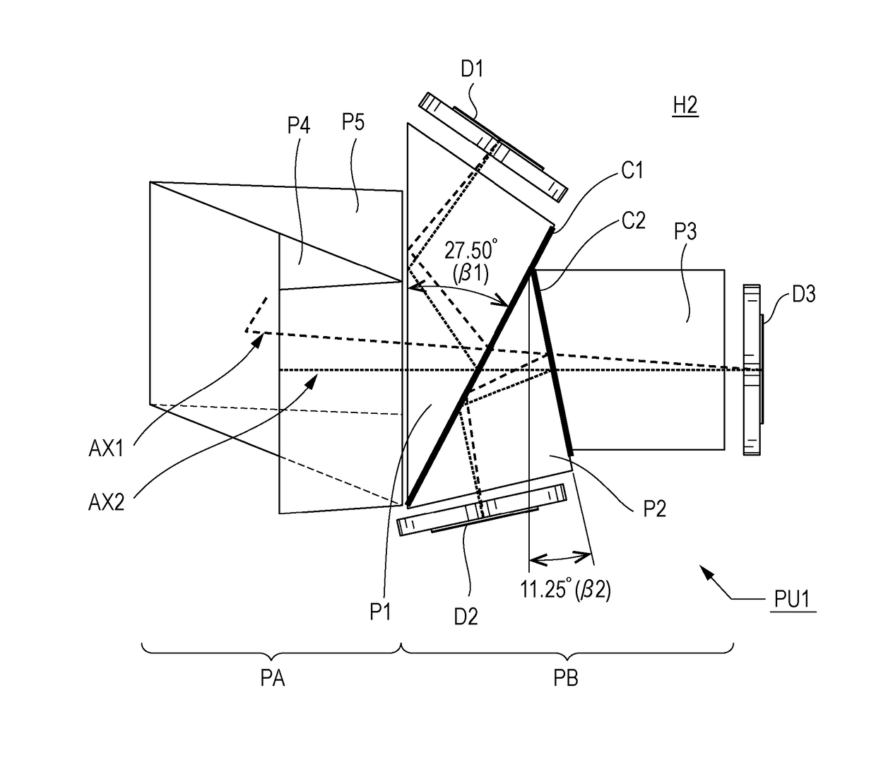
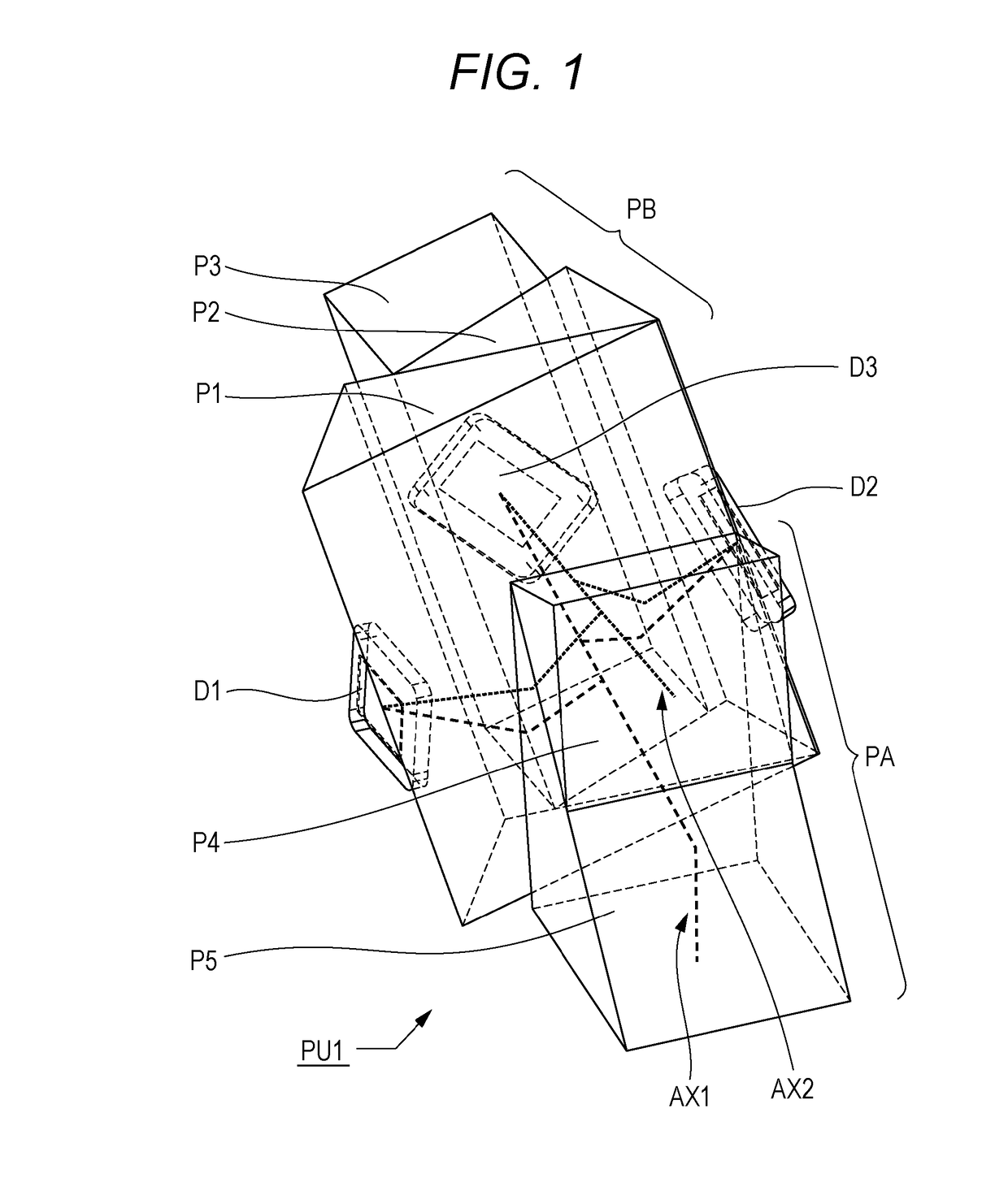
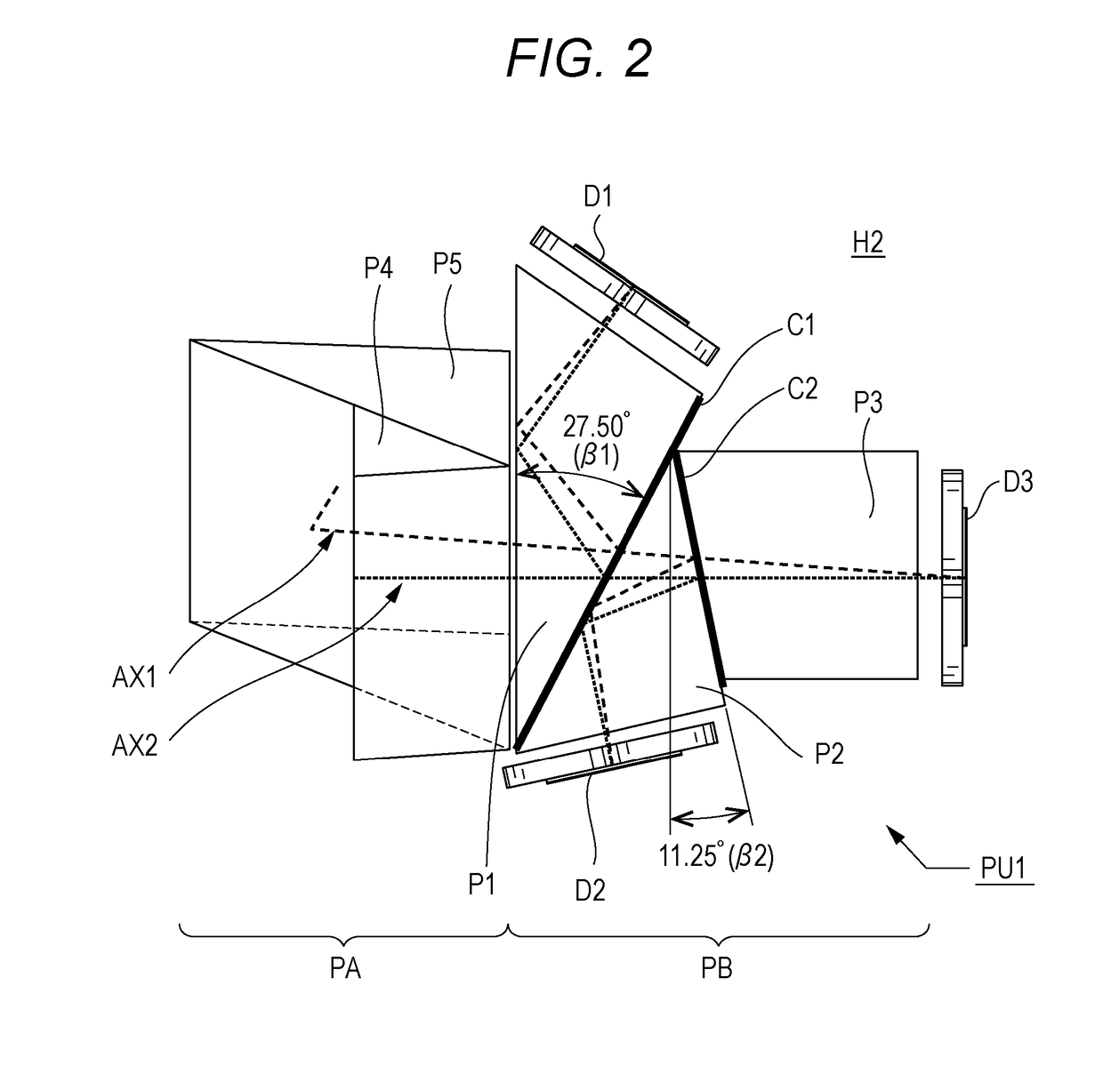
[0037]FIGS. 1 to 4 illustrate a first embodiment of an optical system PU1. FIG. 1 illustrates the optical system PU1 viewed from an obliquely upward direction. FIG. 2 illustrates the optical system PU1 viewed from a top side. FIG. 3 illustrates the optical system PU1 viewed from a lateral side. FIG. 4 illustrates the optical system PU1 viewed from a front side. FIG. 5 illustrates an exemplary schematic configuration of a projector PJ equipped with the optical system PU1. The projector PJ includes, as illustrated in FIG. 5, a projection optical system LN, the optical system PU1, a light source 11, an illumination optical system 12, a control ...


PUM


Abstract

A three-plate image projecting optical system that has a compact and simple configuration and achieves enhanced luminance efficiency and reduction of light quantity loss on the dichroic coating, and a projector equipped with the optical system. The optical system includes a color separating / combining prism having a first / second dichroic coatings, and a first to third digital micromirror devices. A first plane including an illumination light axis and a projection light axis on an image display surface of the third digital micromirror device and a second plane including a surface normal of the first / second dichroic coatings and a surface normal of a center of the third digital micromirror device are relatively rotated with respect to each other from orthogonal states toward a direction in which an incident angle of the illumination light axis with respect to the first dichroic coating or the second dichroic coating is decreased.

Description

BACKGROUND[0001]1. Field of the Invention[0002]The present invention relates to a three-plate optical system and a projector, for example, a three-plate image projection optical system equipped with a reflective display element such as a digital micromirror device and with a color separating / combining prism, and a projector including the three-plate image projection optical system.[0003]2. Description of Related Art[0004]A digital micromirror device is known as a reflective display element mounted on a projector. The digital micromirror device includes an image display surface formed with a plurality of microscopic micromirrors. On the image display surface, the digital micromirror device controls tilt of each of mirror surfaces to modulate intensity of illumination light, thereby forming an image. An ON / OFF of each of pixels of the digital micromirror device is indicated, for example, by mirror surface pivoting of ±12° around a rotation axis forming an angle of 45° with respect to ...

Claims


Application Information

Patent Timeline
Patent Type & Authority Patents(United States)
IPC IPC(8): G03B21/62H04N9/31G03B21/20G02B27/14G02B26/08G03B21/00G03B33/12
CPCH04N9/3158G02B26/0833G02B27/141G02B27/145H04N9/315G03B21/005G03B21/2066G03B33/12H04N9/3105G02B27/148
Inventor TERADA, MASAHIRO
Owner KONICA MINOLTA INC
Why Eureka
Try Eureka