Food dehydrator

a food and dehydrator technology, applied in the direction of drying machines, drying machines with materials at rest, light and heating apparatus, etc., can solve the problems of unsatisfactory increase in power consumption, difficult to maintain the drying temperature of food constant, and possible fire hazards, so as to achieve excellent drying efficiency, reduce power consumption, and improve the effect of drying quality

Active Publication Date: 2018-01-30
HA WEH GU
View PDF4 Cites 7 Cited by
  • Summary
  • Abstract
  • Description
  • Claims
  • Application Information

AI Technical Summary

Benefits of technology

[0010]Accordingly, the present invention has been made in view of the above-mentioned problems occurring in the prior art, and it is an object of the present invention to provide a food dehydrator that adopts an air flowing system wherein air is introduced from the rear surface thereof in such a manner as to be moved forwardly and circulates a portion of the wet steam discharged from a dry room to the dry room again, without discharging to the outside, thus providing a good quality of drying, excellent drying efficiencies, and substantially reduced power consumption.
[0011]It is another object of the present invention to provide a food dehydrator wherein an inner plate made of stainless steel is disposed on the inner side of a front door so as to evenly provide the wavelength of light for the whole food by using the scattered reflection of light generated from a heating member, thus enhancing the dry efficiency.

Problems solved by technology

Accordingly, the closest food to the air supply source is very dried, but the most distant food from the air supply source is more slowly dried, so that drying qualities are different in accordance with the positions of the dry stands, thus undesirably increasing an amount of power consumed.
Further, the conventional food dehydrator may cause the water drops of food falling from the dry stands to pollute the motor and the heat wires of the heat source located at the lower portion thereof, and particularly, if drying for meat is conducted, fire danger may exist due to the lipid droplets generated from the meat.
Further, generally coil type heat wires are exposed directly to the food to be dried, thus causing irregular drying and making it hard to maintain the drying temperature of the food constantly.

Method used


Image

  • Food dehydrator
  • Food dehydrator
  • Food dehydrator

Examples


Embodiment Construction

[0036]Hereinafter, a food dehydrator according to the present invention will be in detail explained with reference to the attached drawings.

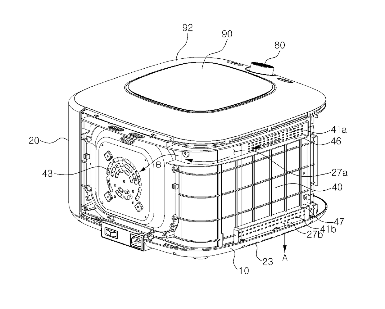
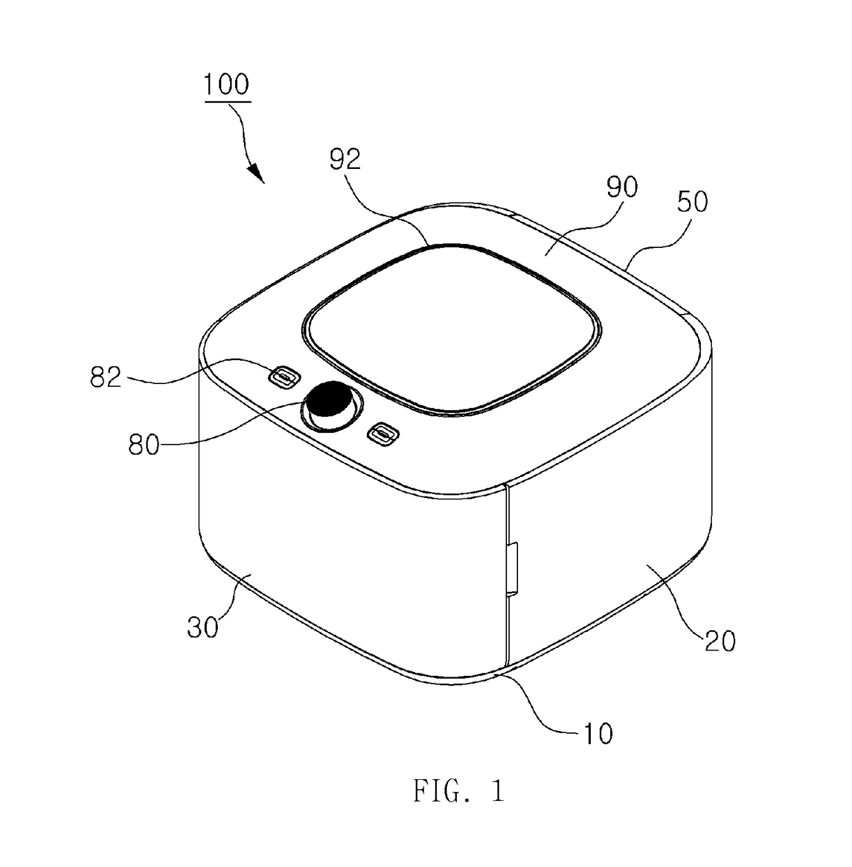
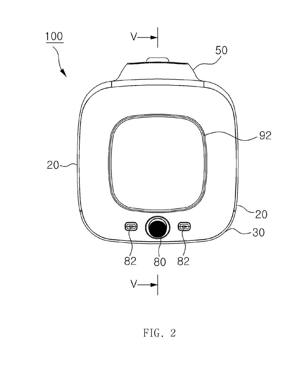
[0037]As shown in FIGS. 1 to 4, a food dehydrator 100 largely includes a body and a front door 30 detachably mounted on the front surface of the body. The body includes a base member 10, the front door 30, side casings 20 disposed on both sides of the front door 30, a rear casing 50 connected between the side casings 20, and a top casing 90 coupled to the top sides of the body and the front door 30. Further, the body has a dry room 21 as will be described later formed at the inside thereof so as to dry food therein.

[0038]The base member 10 is located at the bottom of the body and coupled to the front door 30, the side casings 20 and the rear casing 50 along the top ends thereof. Further, the base member 10 has a plurality of body supporters 24 formed spaced apart from each other on the underside thereof so as to allow the base member 10 to be fi...


PUM


Abstract

The present invention relates to a food dehydrator including: a body having a front door detachably mounted on the front surface thereof, a plurality of air inlet holes formed on the rear surface thereof and a plurality of body air discharge holes formed on the side surfaces thereof; an inner casing having a dry room formed at the internal space thereof, a plurality of inner casing air inlet holes formed on the rear surface thereof, a plurality of first air outlet holes and second air outlet holes formed on the side surfaces thereof; a fan adapted to supply the external air to the dry room; and a heating member disposed behind the fan along an air flowing path so as to heat the air supplied to the dry room.

Description

BACKGROUND OF THE INVENTION[0001]Field of the Invention[0002]The present invention relates to a food dehydrator that can simply dry all kinds of food, such as fruit, vegetables, agricultural products, meat, fish, and so on.[0003]Background of the Related Art[0004]Conventional food drying is carried out in open places exposed to air and sun, but recently, food drying is conducted through a mechanical food dehydrator.[0005]Such food dehydrator is configured wherein in a state wherein a plurality of shelves on which food to be dried are put is inserted thereinto, air is absorbed from inlets and circulated entirely in the food dehydrator by using a fan driven by a motor. In this case, it is very important that the internal air in the food dehydrator which is raised in humidity due to water vapor should be discharged to the outside and at the same time dry and fresh external air should be introduced into the food dehydrator. Accordingly, the food dehydrator generally has air inlet holes ...

Claims


Application Information

Patent Timeline
Patent Type & Authority Patents(United States)
IPC IPC(8): A23L3/40F26B9/06F26B9/00
CPCA23L3/40F26B9/066F26B9/003F26B2200/02
Inventor HA, WEH GU
Owner HA WEH GU
Why Eureka
Try Eureka