Sensor system, mote and a motes-system for sensing an environmental parameter

a sensor system and environmental parameter technology, applied in the field of sensor systems, can solve the problems of quite different requirements for the sensor system, achieve the effects of minimal energy and space, improved identification of the timing of the sensed value, and low cost of the sensor system

Active Publication Date: 2018-01-30
INGU SOLUTIONS INC
View PDF14 Cites 2 Cited by
  • Summary
  • Abstract
  • Description
  • Claims
  • Application Information

AI Technical Summary

Benefits of technology

[0013]To allow the sensor system to operate for the predefined time duration—which typically is a few days—in the remote environments while contained in such small container, also the requirements to the energy storage are rather constrained such that standard batteries may not be useable. In addition, any energy consumption should be minimized. As such, the inventors have designed a specific sensor system architecture in which the energy storage comprises a chargeable capacitor which may be charged via electro-magnetic radiation received via the on-board antenna. Subsequently the sensor system is configured for initiating the sequence of sensed values when the energy storage is charged or when the energy storage is being charged. This combination of features allows an appropriate charging of the energy storage of the sensor system and also allows for a time calibration of the sensed environmental parameter at the time the energy storage is being charged or is (fully) charged. This omits the need for an activation switch or for a control signal for initiating the sequence of sensed values. For example, the timer may be initiated when the energy storage is more than 10% charged, or more than 50% charged or more than 80% charged. So the sensor system may be automatically activated while the energy storage is being charged. Using the sequence of sensed values, together with the predetermined time interval between subsequent time triggers (and so between subsequent sensed values in the sequence of sensed values) and the initiation time at which the sequence of sensed values has been started (triggered by the energy storage being charge or is fully charged), the exact time at which each of the sensed values is sensed by the sensory system can be determined sufficiently accurate and relatively easy.
[0014]A further benefit when using the sensor system according to the invention is that the claimed configuration may also be used to enable an easy synchronization of the sensor system to other similar sensor systems. The synchronization is almost automatically done when, for example, each sensor system is simultaneously charged, for example, when all sensor systems at the same time are subject to the same electro-magnetic radiation for charging the on-board energy storage of each of the sensor systems. As indicated in the sensor system according to the invention, the sensor system is configured to initiate the sequence of sensed values when the energy storage is charged or when the energy storage is being charged. When each of the similar sensor systems are further configured to have the same predetermined time interval between subsequent time triggers, the plurality of similar sensor systems all measure their sensed values (representing their specific environmental parameter) substantially at the same time. So each corresponding sensed value in the sequence of sensed values in each of the similar sensor systems that have been charged using the same electro-magnetic radiation is sensed substantially at the same time. The similar sensor systems may have similar configuration as the sensor system according to the invention, but may, for example, sense a different environmental parameter compared to the sensor system. For example, the sensor system according to the invention may sense an ambient temperature around the sensor system during the predefined time duration, while some of the similar sensor systems may, for example, sense an ambient pressure surrounding the similar sensor system during the predefined time duration. When the sensor system together with the similar sensor systems migrate through the remote environment some information about the environmental parameter along the route taken by the sensor system and by the similar sensor system may be analyzed. So when using a plurality of such sensor systems, the design of the sensor system according to the invention enables to get synchronized readings from each of the plurality of sensor systems of their environmental parameters and allows a very small efficient sensor system which can migrate through narrow passage ways in the remote environment and which is chargeable.
[0017]In an embodiment of the sensor system, the sensor system is configured for storing a trigger number together with each sensed value, the trigger number being generated by the timer and indicating the number of time triggers generated by the timer since the resetting of the timer. The trigger number may, for example, be generated by the counter. Using such trigger number and storing the trigger number together with the sensed value in the storage element allows an improved identification of the timing of the sensed value. Using the trigger number, the timing of the sensed value is not only defined by its place in the sequence of sensed values, but is also defined by the associated trigger number stored together with the sensed value.
[0018]In an embodiment of the sensor system, the sensor system further comprises a controller for controlling the operation of the sensor system. In an embodiment of the controller, the controller is a state machine. In general, a state machine as used in embodiments of this invention is any device that stores a status or value of something at a given time. In a more advanced version of the controller or state machine, the controller or state machine may be able to receive input and may use this input to change the status or way of working of the system dependent on the received input. A state machine may be preferred as controller because such state machines often comprise only a limited number of logic circuits, often dedicated to the required controlling, such that a minimal amount of energy and space is required. Of course if energy and space limitations allow, also other types of controllers may be used in the sensor systems according to the invention. The controller used in the embodiment of the invention may, for example, ensure that the sensor takes a sensed value at each time trigger generated by the timer and that the sensed value (possibly including the trigger number) is subsequently stored in the storage element. The storage element may, for example, be a shift register in which the sensed values are sequentially stored as they are measured by the sensor. Using such a controller and shift register in the sensor system according to the current invention, the sensor system may be miniaturized and produced at a relatively low cost. Due to these small dimensions and relatively low cost, such sensor systems are specifically beneficial when used in a swarm of sensor systems which swarm the remote environment and sense environmental parameters at each of their individual locations within the remote environment.
[0019]In an embodiment of the sensor system, the controller is constituted of one or more logic blocks. As indicated before, the relatively stringent dimension requirements to enable the sensor system to move through narrow passageways in, for example, sewer systems or oil wells, together with the power requirements to enable operation during the predefined time duration also require the controller to have very small dimensions and very low power consumption. Constituting the controller of a few logic blocks would minimize the power required to run the sensor system and would allow the sensor system, including controller, to be contained in such small containers.
[0021]In an embodiment of the sensor system, the controller is coupled to the antenna and is configured to communicate via the antenna. Using the antenna both for charging the energy storage and for communication of the controller with the outside further reduces the overall elements required to allow the sensor system to function, which further contributes to the miniaturization of the sensor system. Furthermore, no connectors are necessary for connecting the controller or any other element of the sensor system to the outside. So both the charging and communication is done wirelessly using the same antenna to further enable cost reduction and miniaturization.

Problems solved by technology

However, when sensing the environmental parameters in a remote location, the requirements to the sensor system are quite different.
However, in some remote environments, such as, for example, oil wells or sewer systems in cities, the GPS signal does not reach the individual motes and other means of measuring the environment parameter have to be found.

Method used


Image

  • Sensor system, mote and a motes-system for sensing an environmental parameter
  • Sensor system, mote and a motes-system for sensing an environmental parameter
  • Sensor system, mote and a motes-system for sensing an environmental parameter

Examples


Embodiment Construction

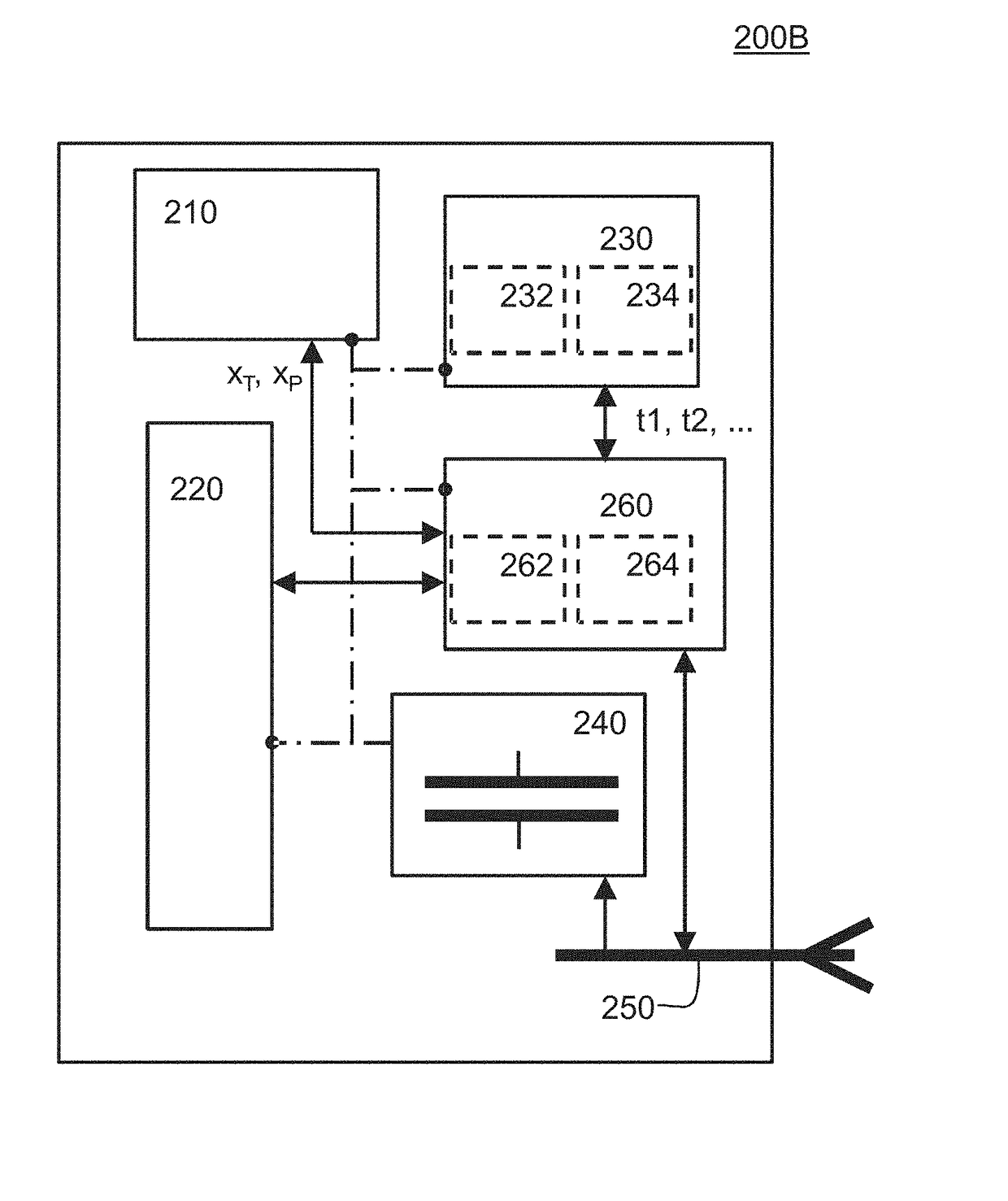
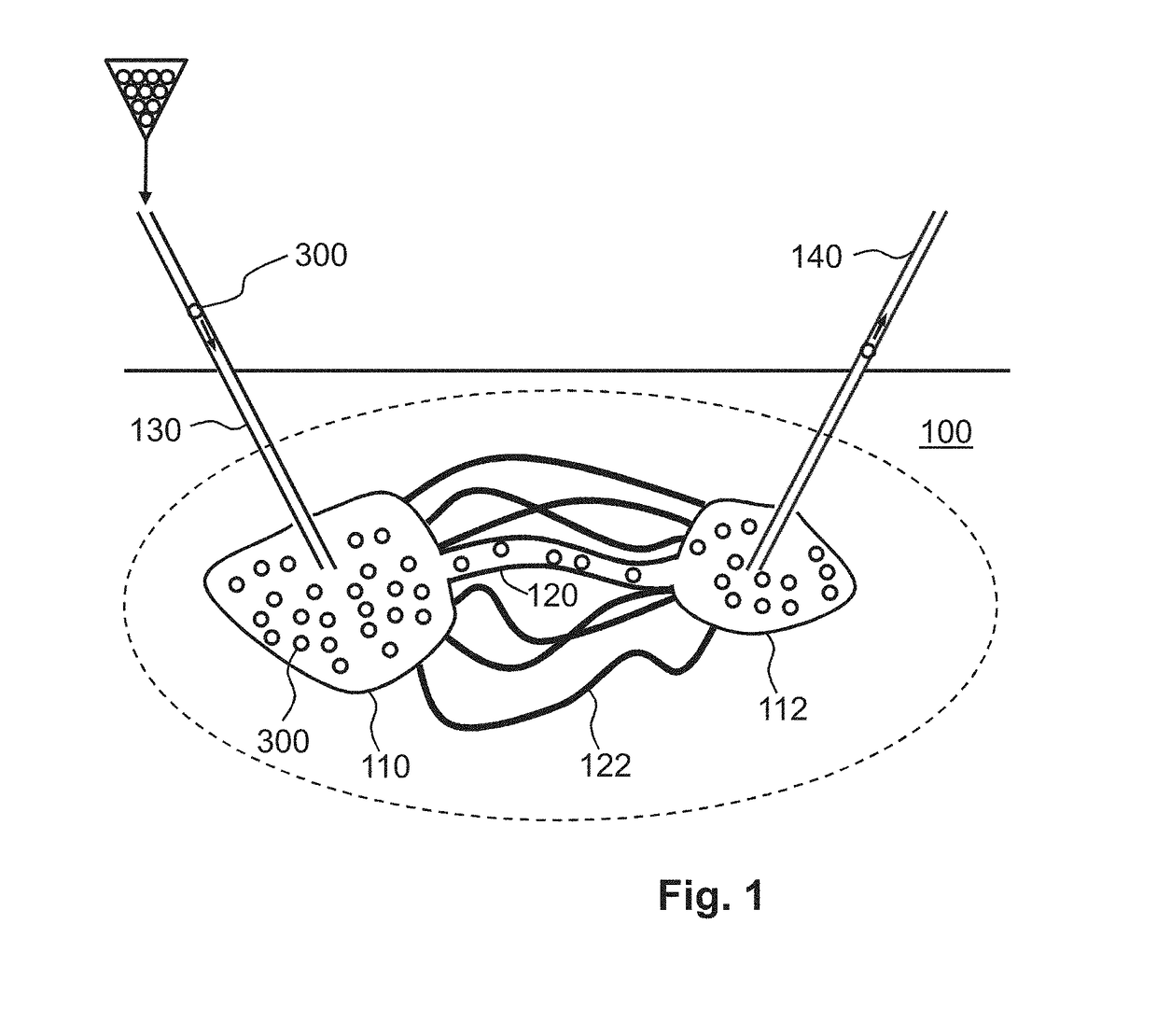
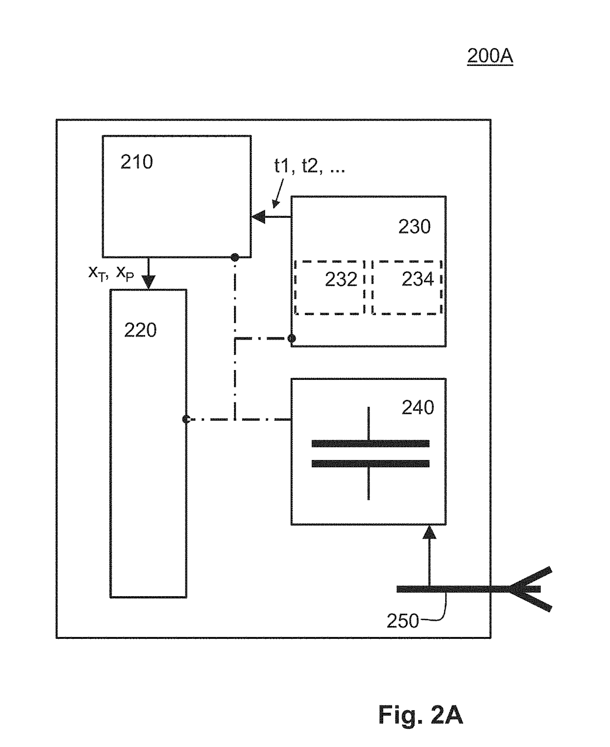
[0037]FIG. 1 shows an environment 100 in which a mapping is required. The environment 100 shown in FIG. 1 represents an oil well 100 having a first cavity 110 which is connected to a second cavity 112 via a main passageway 120 and a plurality of smaller passageways 122. FIG. 1 further shows a plurality of motes 300 which are injected via an injection pipe 130 and which may be harvested via an extraction pipe 140. The motes 300 contain a sensor system 200A, 200B (see FIGS. 2A and 2B) which are contained in a spherical container (see FIG. 4A). Each of the motes 300 may, for example, be injected into the oil well 100 via the injection pipe 130 using a stream of hot water (not shown) which may, for example, be used to dilute some of the treacle cured oil to allow more of the treacle crude oil to be harvested. The stream of hot water typically has a temperature close to the boiling temperature of water. The motes 300 are designed to float or be buoyant in the injected liquid such that th...


PUM

PropertyMeasurementUnit
time durationaaaaaaaaaa

Abstract

The invention provides a sensor system, mote and a motes-system. The sensor system is configured for being contained in a container having a maximum outer dimension less than 10 millimeter and for sensing at least one environmental parameter (T, P, pH, ρ). The sensor system includes at least one sensor configured for measuring the at least one environmental parameter and for generating a sensed value (xT, xP). The sensor system includes a storage element and a timer in which the at least one sensor is configured to measuring the at least one environmental parameter at each time triggers (t1, t2, . . . ) from the timer and for storing a sensed value (xT, xP). The sensor system further includes an energy storage comprising a chargeable capacitor being chargeable via electro-magnetic radiation of a predefined frequency, and wherein the sensor system is configured to initiate a sequence of sensed values when the energy storage is charged or is being charged.

Description

CROSS REFERENCE TO RELATED APPLICATION[0001]This application claims the priority benefit under 35 U.S.C. § 119 of Netherlands Patent Application No. 2012484, filed on Mar. 20, 2014, which is hereby incorporated in its entirety by reference.FIELD OF THE INVENTION[0002]The invention relates to a sensor for mapping an environmental parameter. The invention further relates to a mote and a motes-system.BACKGROUND ART[0003]Sensors for sensing an environmental parameter are well known and used throughout our current environment. Only one of the many examples used in today's world may, for example, be a temperature sensor which may, for example, be applied in a car for providing temperature information to the driver of the car or to the on-board computer of the car. Such a sensor draws its power from the overall power system of the car and uses the on-board wiring to provide the sensed value to the display of the car or to the on-board computer. However, when sensing the environmental param...

Claims


Application Information

Patent Timeline
Patent Type & Authority Patents(United States)
IPC IPC(8): G01N33/18H02J7/34H02J7/02H02J50/80G01D9/02H02J50/40H02J50/20
CPCG01N33/1886G01D9/02H02J7/025H02J50/20H02J50/40H02J50/80H02J7/34H02J7/345
Inventor WORTCHE, HEINRICH JOHANNESTALNISHNIKH, ELENAVAN POL, JOHANNES HUBERTUS GERARDUS
Owner INGU SOLUTIONS INC
Why Eureka
Try Eureka