Method and system for timing analysis with adaptive timing window optimization for determining signal integrity impact

a timing analysis and adaptive timing technology, applied in the field of timing analysis with adaptive timing window optimization for determining signal integrity impact, can solve the problems of undue optimism in gba slacks, excessive delay, undue optimism in timing analysis, etc., and achieve the effect of reducing undue optimism and pessimism

Active Publication Date: 2018-01-30
CADENCE DESIGN SYST INC
View PDF13 Cites 11 Cited by
  • Summary
  • Abstract
  • Description
  • Claims
  • Application Information

AI Technical Summary

Benefits of technology

[0014]It is an object of the present invention to provide a method and system for simply yet effectively carrying out timing analysis for an electronic circuit design which alleviates undue pessimism and optimism.

Problems solved by technology

Negative slack would indicate excessive delay in the timing path leading to that node requiring remedial measures to avoid detrimental effect on the speed of overall circuit operation.
Yet the reliability of timing analysis is plagued by sources of undue pessimism and optimism.
But optimism is intrinsic to the path mode of such SI analysis; and, this optimism tends for example to cause undue optimism in GBA slacks.
Conversely, pessimism is intrinsic to the overlap mode of such SI analysis; and, this pessimism tends for example to cause undue pessimism in GBA slacks.

Method used


Image

  • Method and system for timing analysis with adaptive timing window optimization for determining signal integrity impact
  • Method and system for timing analysis with adaptive timing window optimization for determining signal integrity impact
  • Method and system for timing analysis with adaptive timing window optimization for determining signal integrity impact

Examples


Embodiment Construction

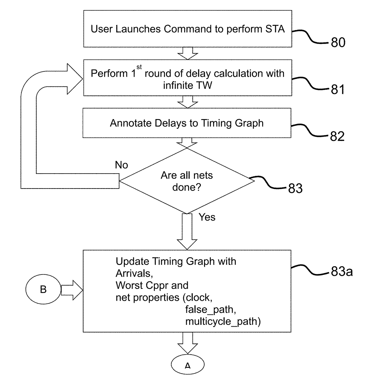
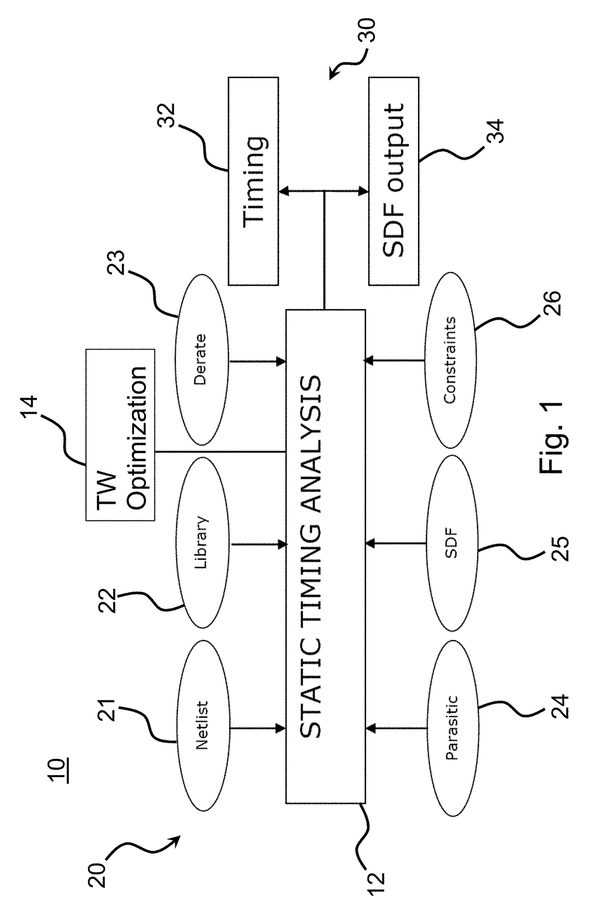
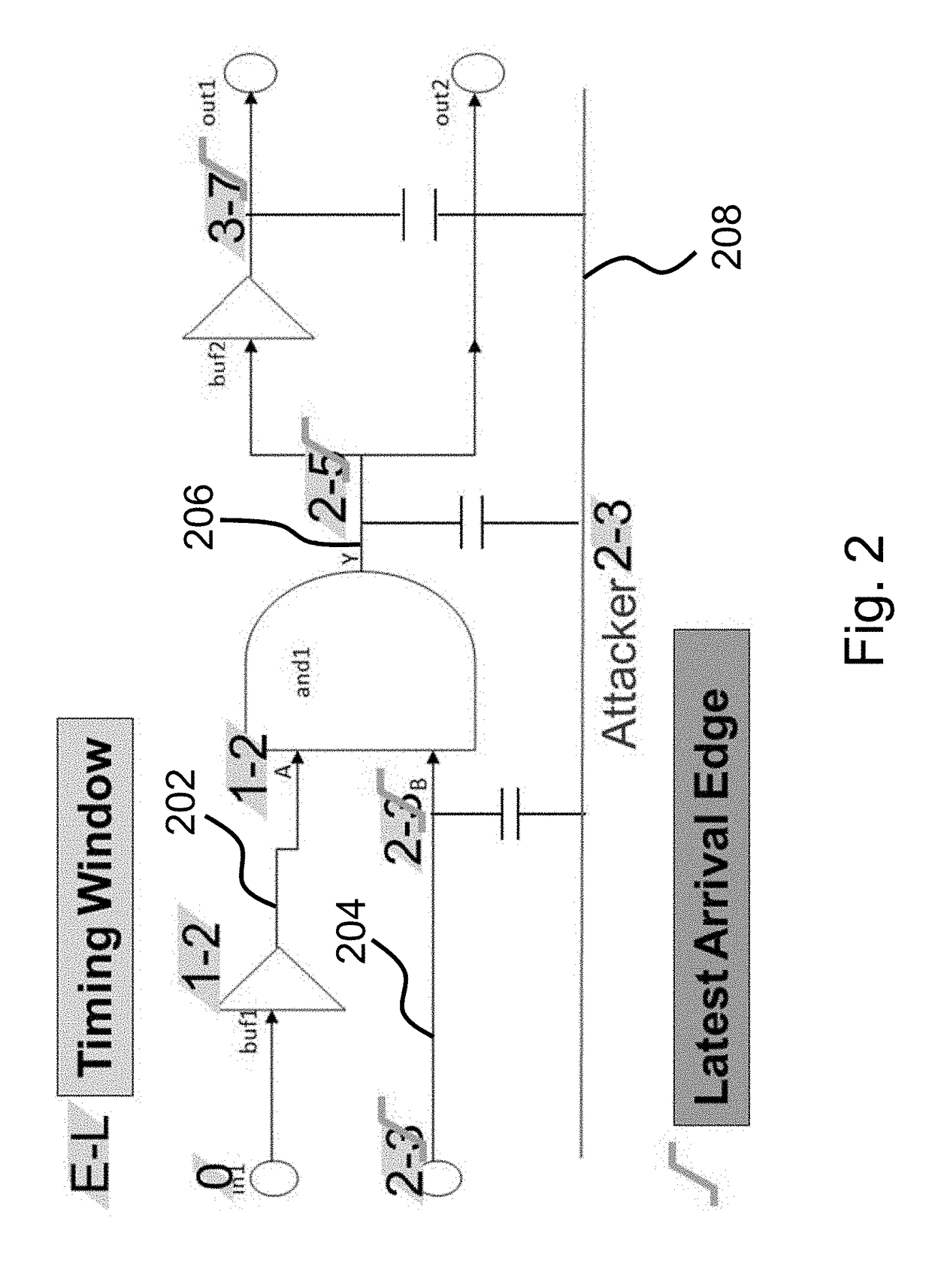
[0035]Briefly, the subject method and system provide for timing analysis of an electronic circuit design which accurately and efficiently takes into account such signal integrity effects as crosstalk on the timing characteristics of circuit operation. The system and method provide for execution of a timing analysis engine incorporates suitable SI analysis measures based on adaptively adjusted timing windows for certain crosstalk-coupled nodes of the electronic circuit design. Undue pessimism or optimism is thereby reduced in the crosstalk delay computed for certain timing paths defined through cells of the electronic circuit design, and the reliability of timing verification (for compliance with applicable constraints) accordingly preserved.

[0036]In accordance with certain aspects of the present invention, the timing analysis engine incorporates timing window optimization measures in support of the crosstalk delay computation executed as part of the static timing analysis it carries...


PUM


Abstract

A method and system are provided for timing analysis of an electronic circuit design. A timing graph defines a plurality of timing paths through different subsections of the electronic circuit design. A timing window is defined for each of the nodes included in a timing path. At least one preliminary round of a predetermined signal integrity analysis is executed on the circuit design based on the timing windows to identify at least one pair of crosstalk-coupled victim and aggressor nodes. Each victim node's timing window is adaptively adjusted according to a predetermined timing property thereof. At least one primary round of the predetermined signal integrity analysis is executed on the electronic circuit design based in part on this adaptively adjusted timing window for each victim node to generate a delay, which is annotated to the timing graph. A predetermined static timing analysis is executed based on the delay-annotated timing graph.

Description

BACKGROUND OF THE INVENTION[0001]The subject method and system are generally directed to efficient yet accurate timing analysis for an electronic circuit design to verify compliance with the various timing constraints applicable thereto. More specifically, the subject method and system provide for optimization of timing windows for certain nodes of the electronic circuit design to facilitate the determination of certain signal integrity effects on timing, such as those due to crosstalk. The subject method and system thereby alleviate undue pessimism or optimism in the computation of such effects for certain timing paths defined through the electronic circuit design.[0002]Various static timing analysis measures are known in the art. A static timing analysis (STA) is carried out to assess the timing of digital circuits using software techniques and certain models that provide relevant characteristics of the circuit in question. Electronic Design Automation (EDA) is widely employed for...

Claims


Application Information

Patent Timeline
Patent Type & Authority Patents(United States)
IPC IPC(8): G06F9/455G06F17/50
CPCG06F17/5081G06F2217/84G06F2217/82G06F30/3312G06F2119/10
Inventor GOYAL, RATNAKARVERMA, MANUJKELLER, IGORVEERAVALLI, ARVIND NEMBILI
Owner CADENCE DESIGN SYST INC
Why Eureka
Try Eureka