Single fuel cell, fuel cell stack, and method of manufacturing fuel cell stack
a fuel cell and single-cell technology, applied in the field of single-cell fuel cells, fuel cell stacks, and methods of manufacturing fuel cell stacks, can solve the problems of affecting power generation performance, no measures are taken to reduce electrical contact resistance, etc., and achieve the effect of electrical contact resistance of a connection portion
- Summary
- Abstract
- Description
- Claims
- Application Information
AI Technical Summary
Benefits of technology
Problems solved by technology
Method used
Image
Examples
first embodiment
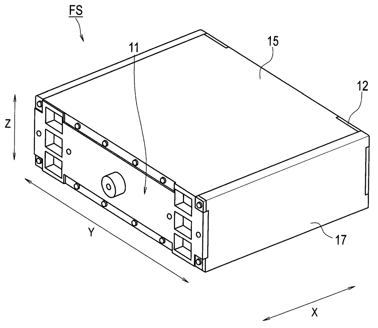
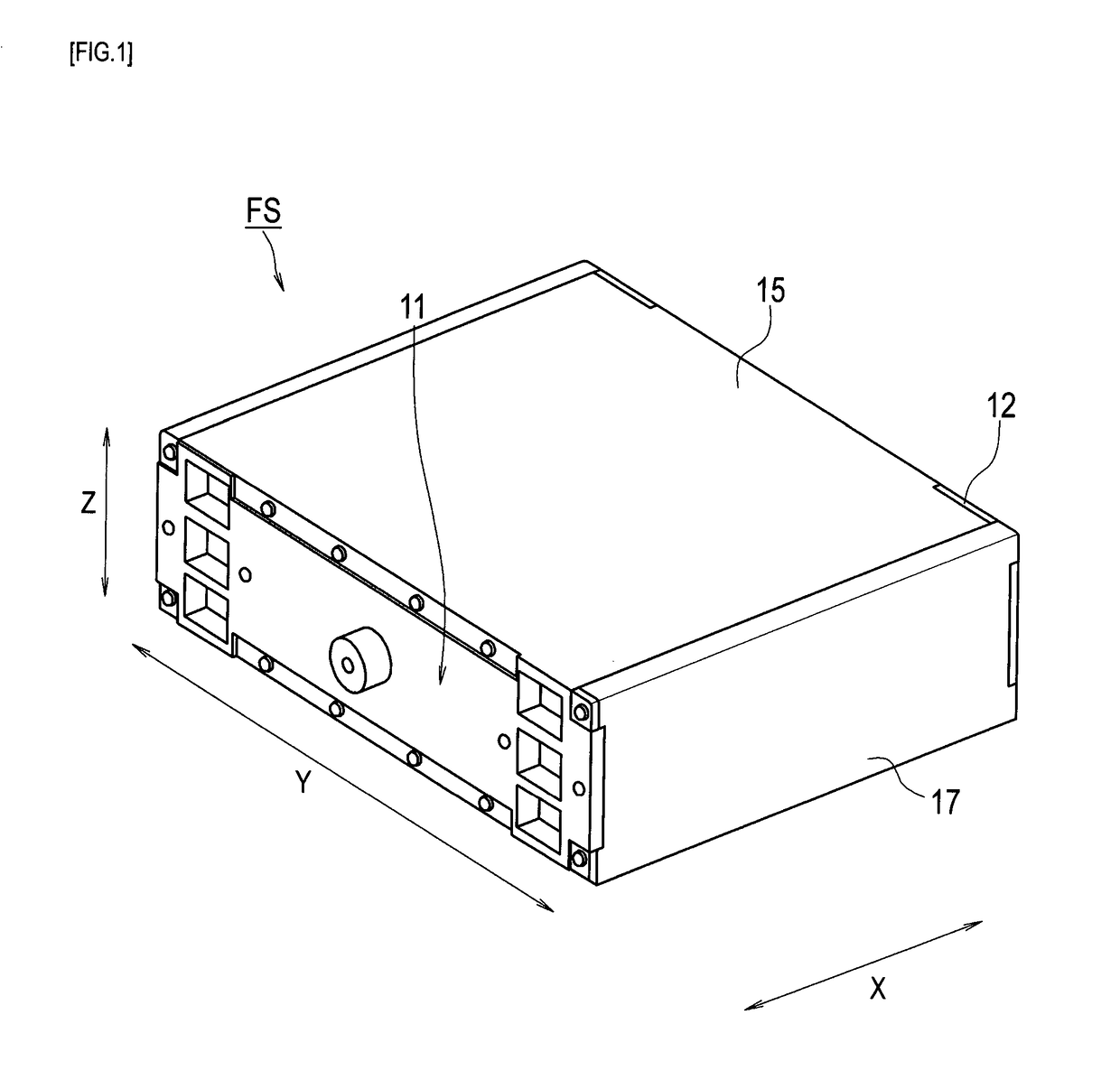
[0033]An embodiment of a single fuel cell and a fuel cell stack of the present invention is described below based on the drawings. The single fuel cell and the fuel cell stack in the embodiment are a polymer electrolyte single fuel cell and a polymer electrolyte fuel cell stack which are configured to be mounted on an electric car and the like.
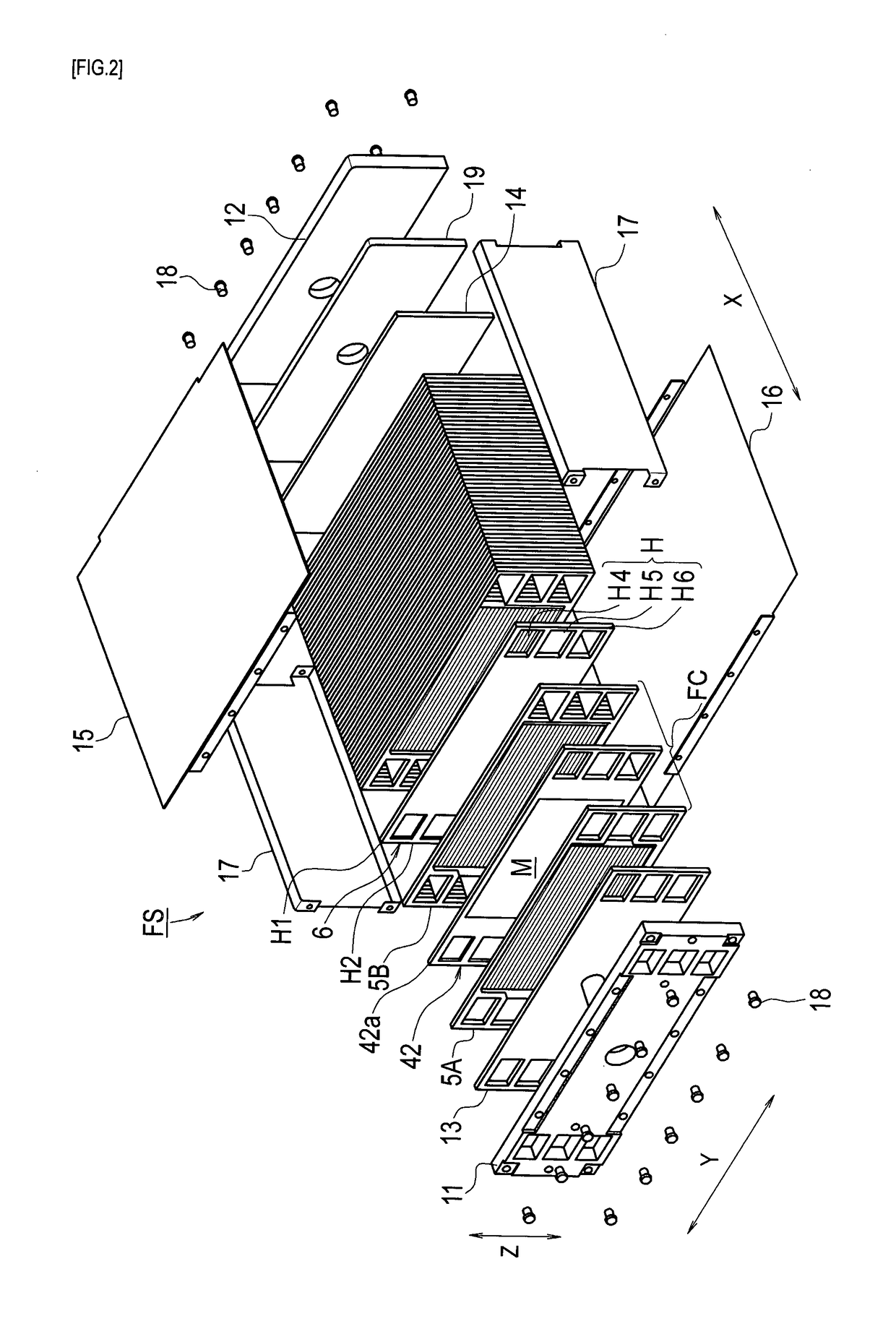
[0034]A fuel cell stack FS shown in FIGS. 1 and 2 has a case integrated configuration in which current collectors 13, 14, multiple single fuel cells FC, and multiple displacement absorbers 6 are stacked between paired end plates 11, 12 and fastened together by using fastening plates 15, 16 and reinforcement plates 17, 17 in such a way that the single fuel cells FC are pressed against each other by the end plates 11, 12. Note that, in the drawings, reference numeral 18 denotes bolts and reference numeral 19 denotes a spacer.
[0035]In each of the single fuel cells FC in the drawings, paired separators 5A, 5B are disposed in such a way that gas pa...
second embodiment
[0068]FIGS. 8A, 8B, and 9 are views for explaining another embodiment of the fuel cell stack of the present invention together with FIGS. 1 to 3. FIG. 8A is an enlarged cross-sectional view of a portion along the I-I line shown in FIG. 3. FIG. 8B is a cross-sectional view of a main portion which shows another example and shows a portion between single fuel cells FC located adjacent to each other when stacked. Therefore, separators 40, 41 shown on upper and lower sides in FIGS. 8A and 8B respectively form part of separate single fuel cells FC on the upper and lower sides.
[0069]Specifically, in each of the single fuel cells FC of the embodiment, the paired separators 40, 41 are disposed in such a way that gas passages for power generation gases to flow are defined and formed respectively on both surface sides of the cell frame 42 shown in FIG. 2. Each of the separators 40, 41 is formed by pressing a metal plate made of stainless steel or the like, and is formed to have substantially t...
third embodiment
[0091]Next, a displacement absorber of another example is described with reference to FIGS. 10A, 10B, and 11. FIG. 10A is an enlarged cross-sectional view of a portion corresponding to the I-I line shown in FIG. 3, and FIG. 10B is a cross-sectional view of a main portion which shows another embodiment. FIG. 11 is a perspective view of part of the displacement absorber shown of the other example. Parts equivalent to those described in the aforementioned embodiments are denoted by the same reference numerals and description thereof is omitted.
[0092]In a displacement absorber 46 shown in FIG. 10A, only the elastic protrusions (spring function portions) 50 are formed integrally with the base plate 51 made of the conductive metal plate described above. In other words, the aforementioned flow-spread preventing protrusions are not provided. In this case also, holding at least part of an end portion 46T of the displacement absorber 46 disposed in a cooling fluid passage F between separators...
PUM
| Property | Measurement | Unit |
|---|---|---|
| adhesion | aaaaa | aaaaa |
| contact resistance | aaaaa | aaaaa |
| electrical contact resistance | aaaaa | aaaaa |
Abstract
Description
Claims
Application Information
 - R&D
- Intellectual Property
- Life Sciences
- Materials
- Tech Scout
- Unparalleled Data Quality
- Higher Quality Content
- 60% Fewer Hallucinations
Browse by: Latest US Patents, China's latest patents, Technical Efficacy Thesaurus, Application Domain, Technology Topic, Popular Technical Reports.
© 2025 PatSnap. All rights reserved.Legal|Privacy policy|Modern Slavery Act Transparency Statement|Sitemap|About US| Contact US: help@patsnap.com


