Phototherapy light engine

a technology of light engine and phototherapy, which is applied in the direction of surgery, transportation and packaging, therapy, etc., can solve the problems of large and cumbersome traditional phototherapy providing devices, inability to be held by hand, and more than 50% of the emitted light may be lost from absorption into surrounding materials, etc., and achieve the effect of low production cos

Active Publication Date: 2018-02-27
ZERIGO HEALTH INC
View PDF108 Cites 12 Cited by
  • Summary
  • Abstract
  • Description
  • Claims
  • Application Information

AI Technical Summary

Benefits of technology

[0005]Described herein are devices, systems, and methods that deliver light for phototherapy to a subject. The devices, systems, and methods described herein are adapted for delivery of phototherapy in terms of their mode of delivery of phototherapy, uniformity of light administered to a treatment site, the power of the photo-output that is achievable, and the relatively low cost of production, among other things.
[0006]The mode of delivery described herein is adapted in that the devices, systems, and methods described herein may be implemented with a hand-held device. Traditional phototherapy providing devices are large and cumbersome, and are thus not suitable for hand held use. Hand held use is advantageous because, for example, it is a convenient mode in terms of ease of use for the subject, and hand held use is additionally advantageous because, for example, hand held use allows a subject to direct therapy directly to an area requiring treatment. Hand held usage is achievable, in part at least, due to the suitability of use of light emitting diodes in providing phototherapy. Light emitting diodes have a very small die size which is typically less than 1 square millimeter. Individually packaged light emitting diodes are also small having a size that is typically less than 15 square millimeters. Light emitting diodes also have the advantage that they can be driven with low voltage electronics that reduces the size of the power electronics and enables the device to be easily driven with a battery-powered supply. The small size of light emitting diodes allows the use of the light emitting diodes in arrays that are themselves relatively small in diameter or in size, and can be combined with other relatively small components to form a unique phototherapy device adapted for hand held use.
[0007]The power of the photo-output that is achievable is also adapted in the devices, systems, and methods described herein. An improved photo-output is advantageous because, for example, it may be expected to decrease treatment time, thus increasing treatment compliance, and is also advantageous because, for example, it may provide a more cost effective treatment. The improved power output is achieved, at least in part, due to the use of thermal control in combination with the use of multiple reflectors and reflector types. It is common for light emitting diode output to drop dramatically as the temperature of the light emitting diode increases. In some cases this output can drop below 50% of the achievable power just from self-heating. Furthermore, controlling the temperature rise may permit the devices described herein to drive light emitting diodes at higher power levels without suffering efficiency losses associated with higher operating temperatures. Additionally, utilizing reflectors may permit the devices described herein to direct the emitted light to the target area with improved efficiency. Light emitting diodes typically output light in all directions and in some cases more than 50% of the emitted light may be lost from absorption into surrounding materials without the use of reflectors.
[0008]The systems and devices described herein are also adapted in terms of cost of production. High cost is generally a barrier to entry in the phototherapeutics market. A lower cost of production is advantageous because, for example, it will allow the device to be provided for home use at an affordable cost. The reduction of cost is achievable, at least in part, because the efficiency gains from the use of thermal control and reflectors allows for a reduction in the number of LEDs for light emissions required for phototherapy.

Problems solved by technology

Traditional phototherapy providing devices are large and cumbersome, and are thus not suitable for hand held use.
Light emitting diodes typically output light in all directions and in some cases more than 50% of the emitted light may be lost from absorption into surrounding materials without the use of reflectors.
High cost is generally a barrier to entry in the phototherapeutics market.

Method used


Image

  • Phototherapy light engine
  • Phototherapy light engine
  • Phototherapy light engine

Examples


Embodiment Construction

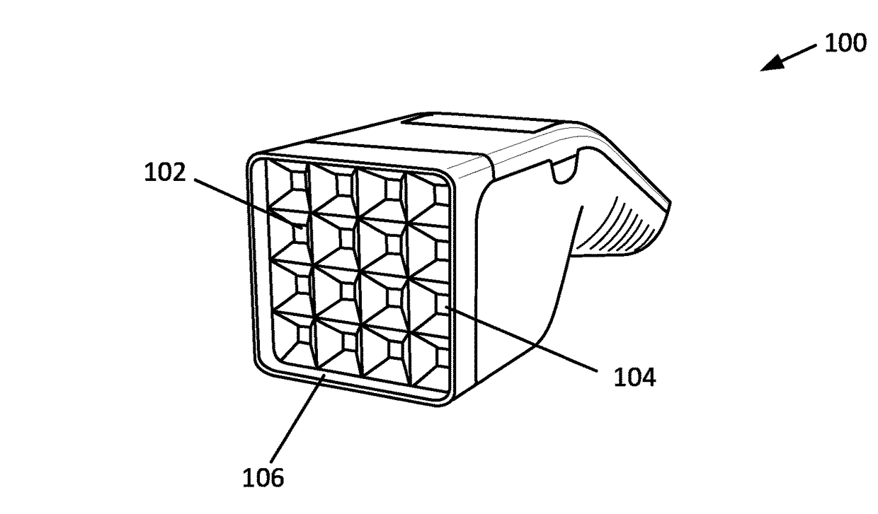
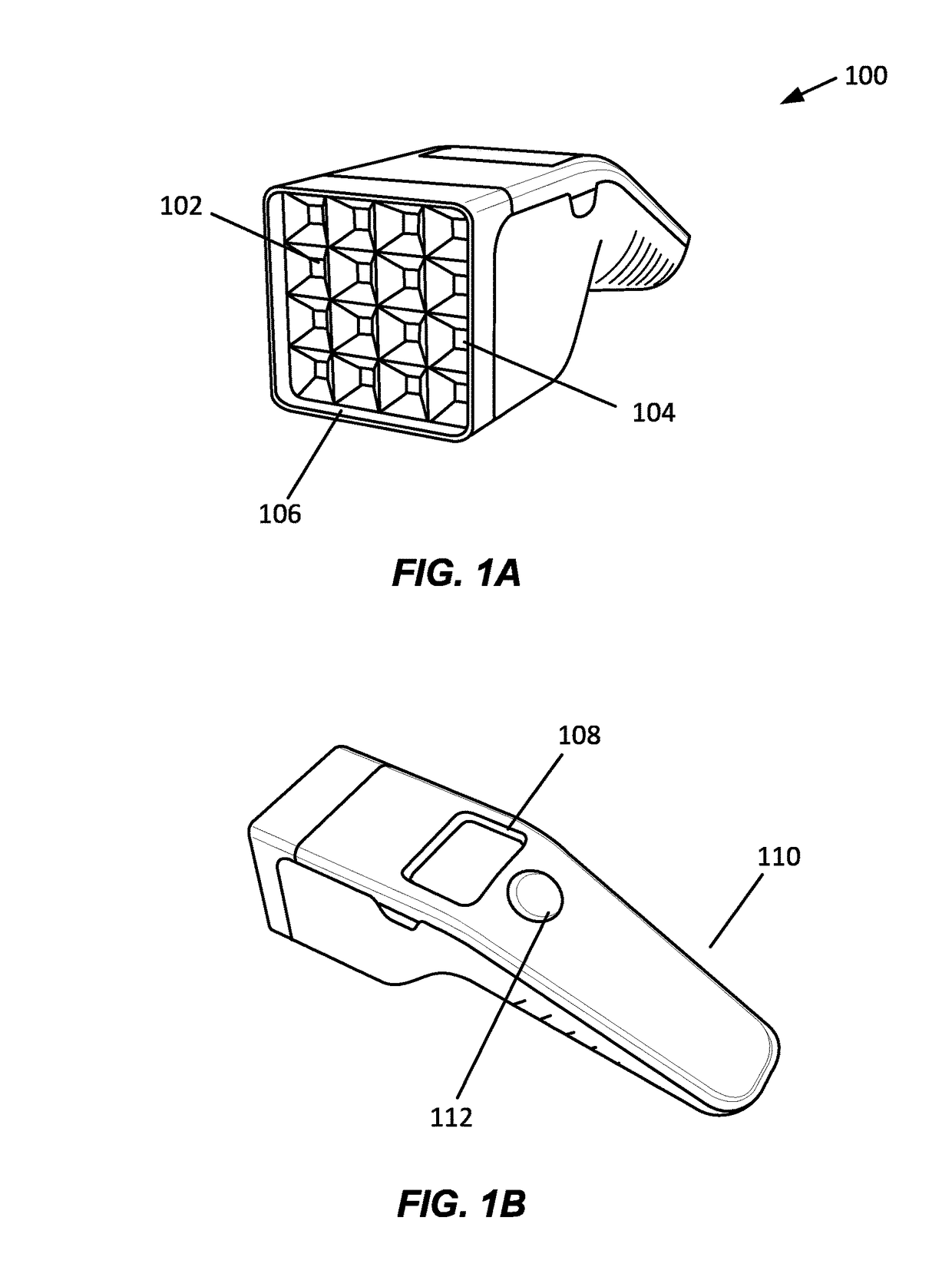
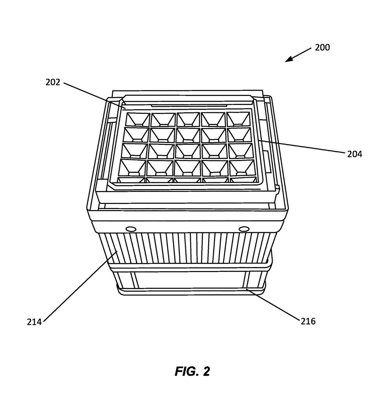
[0022]Described herein are devices, systems, and methods for providing phototherapy to a subject. Before explaining at least one embodiment of the inventive concepts disclosed herein in detail, it is to be understood that the inventive concepts are not limited in their application to the details of construction, experiments, exemplary data, and / or the arrangement of the components set forth in the following description, or illustrated in the drawings. The presently disclosed and claimed inventive concepts are capable of other embodiments or of being practiced or carried out in various ways. Also, it is to be understood that the phraseology and terminology employed herein is for purpose of description only and should not be regarded as limiting in any way.

[0023]In the following detailed description of embodiments of the described subject matter, numerous specific details are set forth in order to provide a more thorough understanding of the inventive concepts. However, it will be app...


PUM


Abstract

Described herein are devices, systems, and methods for delivering phototherapy to a subject. A phototherapy light engine is combined with other components to form a phototherapy system that provides phototherapy treatment to a subject. A phototherapy system may be implemented as a hand held system comprising the light engine that is configured to communicate with a remote computing device.

Description

CROSS-REFERENCE[0001]This application is a Continuation of International Application No. PCT / US2016 / 024996 entitled “PHOTOTHERAPY LIGHT ENGINE” filed Mar. 30, 2016, which claims the benefit of U.S. Provisional Application Ser. No. 62 / 146,124, entitled “PHOTOTHERAPY LIGHT ENGINE” filed on Apr. 10, 2015, the content of which each application is herein incorporated herein by reference in its entirety.BACKGROUND OF THE INVENTION[0002]Phototherapy is exposure of a subject to either natural sunlight or light generated by an artificial light source in order to treat a lesion, disease, or condition of the subject. Certain wavelengths or a range of wavelengths of light have been found to provide optimal therapy for particular lesions, diseases or conditions. The UVB range is an example of a particularly therapeutic range of wavelengths.[0003]Light emitting diodes are a light source that may be used to generate light in a wavelength range suitable for use with phototherapy. A light emitting d...

Claims


Application Information

Patent Timeline
Patent Type & Authority Patents(United States)
IPC IPC(8): A61N5/06H01L33/60H01L33/62H02J7/00H01L33/58H01L25/075H01L33/48H01L33/64A61N5/00A61B34/00
CPCA61N5/0616H01L33/483H01L33/58H01L33/60H01L33/62H01L33/641H01L33/648H02J7/0021H02J7/0044H01L25/0753H01L33/64A61B34/25A61N5/0618A61N2005/005A61N2005/0644A61N2005/0652A61N2005/0661A61N2005/0666A61N2005/0626
Inventor GAMELIN, ANDRE S.GROSS, MARTYN C.SCHMIDT, JACKMACNEISH, III, WILLIAM JACK
Owner ZERIGO HEALTH INC
Why Eureka
Try Eureka