
Controller for driving a motor, and electric power assisted vehicle

a technology of control technology and motor, applied in the direction of electrodynamic brake system, bicycles, transportation and packaging, etc., can solve the problems of difficult to provide intended regenerative braking force by the rider, hand fatigue, and sense of danger for the rider, so as to achieve the effect of stopping regeneration and starting regeneration with eas

Active Publication Date: 2018-02-27
TAIYO YUDEN KK
View PDF20 Cites 0 Cited by
  • Summary
  • Abstract
  • Description
  • Claims
  • Application Information

AI Technical Summary

Benefits of technology

[0013]To achieve these and other advantages and in accordance with the purpose of the present invention, as embodied and broadly described, in one aspect, the present disclosure provides a controller for driving a motor, including: a driving control unit that controls driving of a motor; and a regenerative control unit that instructs the driving control unit to start regeneration when a signal received from a pedal rotation sensor that detects a rotation direction of a pedal indicates that the rotation direction of the pedal is backwards, the regenerative control unit controlling an amount of the regeneration in accordance with a rotation amount of the pedal while the rotation direction of the pedal is backwards, the rotation amount being obtained by the pedal rotation sensor. With this configuration, the rider can start regeneration with ease.
[0014]The regenerative control unit, after instructing the driving control unit to start regeneration, may instruct the driving control unit to stop regeneration when a signal received from the pedal rotation sensor indicates that the rotation direction of the pedal is forward. With this configuration, the rider can stop regeneration with ease.
[0018]The regenerative control unit, after instructing the driving control unit to start regeneration, may instruct the driving control unit to stop regeneration when a signal has been received from a torque sensor indicating that torque has been detected. With this configuration, the burden on the rider can be decreased when propulsion is needed during adjustment of the regeneration control amount.

Problems solved by technology

Bicycles, unlike automobiles and motorcycles, do not have engine brakes, resulting in a sense of danger for the rider when descending long downward slopes at a high speed.
There are problems, however, such as this kind of braking operation being bothersome for the rider, and hand fatigue occurring due to prolonged operation of the brakes.
Meanwhile, it is possible to control regenerative braking through operation of the brakes, but difficult to provide intended regenerative braking force by the rider due to the operation of the brakes being troublesome and due to ordinary brake operation detection devices only being able to detect two states: a state in which the brakes are being operated and a state in which the brakes are not being operated.
There are problems, however, such as the brake wire stretching due to passage of time, mismatch between the operating point of the mechanical brakes and the braking operation amount controlling the regenerative braking force, and the mechanical brakes operating before efficient regenerative braking has occurred, thereby wasting the kinetic energy as heat.
There is also technology that automatically performs regenerative braking according to pre-determined configurations in electric power-assisted vehicles such as in electric bicycles; however, these pre-determined configurations do not necessarily coincide with the intentions of the rider.
Accordingly, depending on the rider, there may be a deceleration that is excessive enough to cause panic, or conversely an insufficient deceleration that causes the rider to feel a sense of danger.

Method used


Image

  • Controller for driving a motor, and electric power assisted vehicle
  • Controller for driving a motor, and electric power assisted vehicle
  • Controller for driving a motor, and electric power assisted vehicle

Examples


embodiment 1

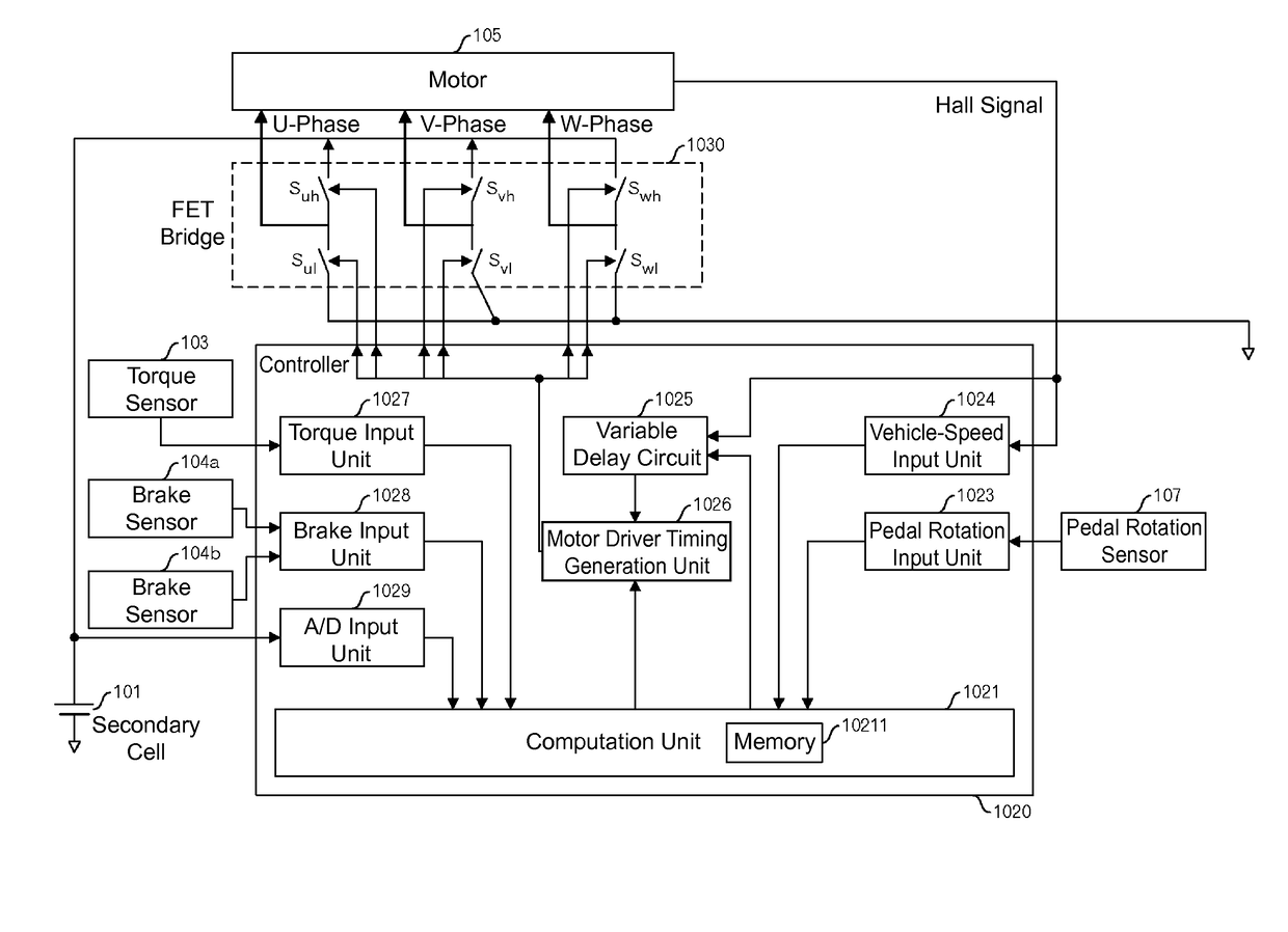
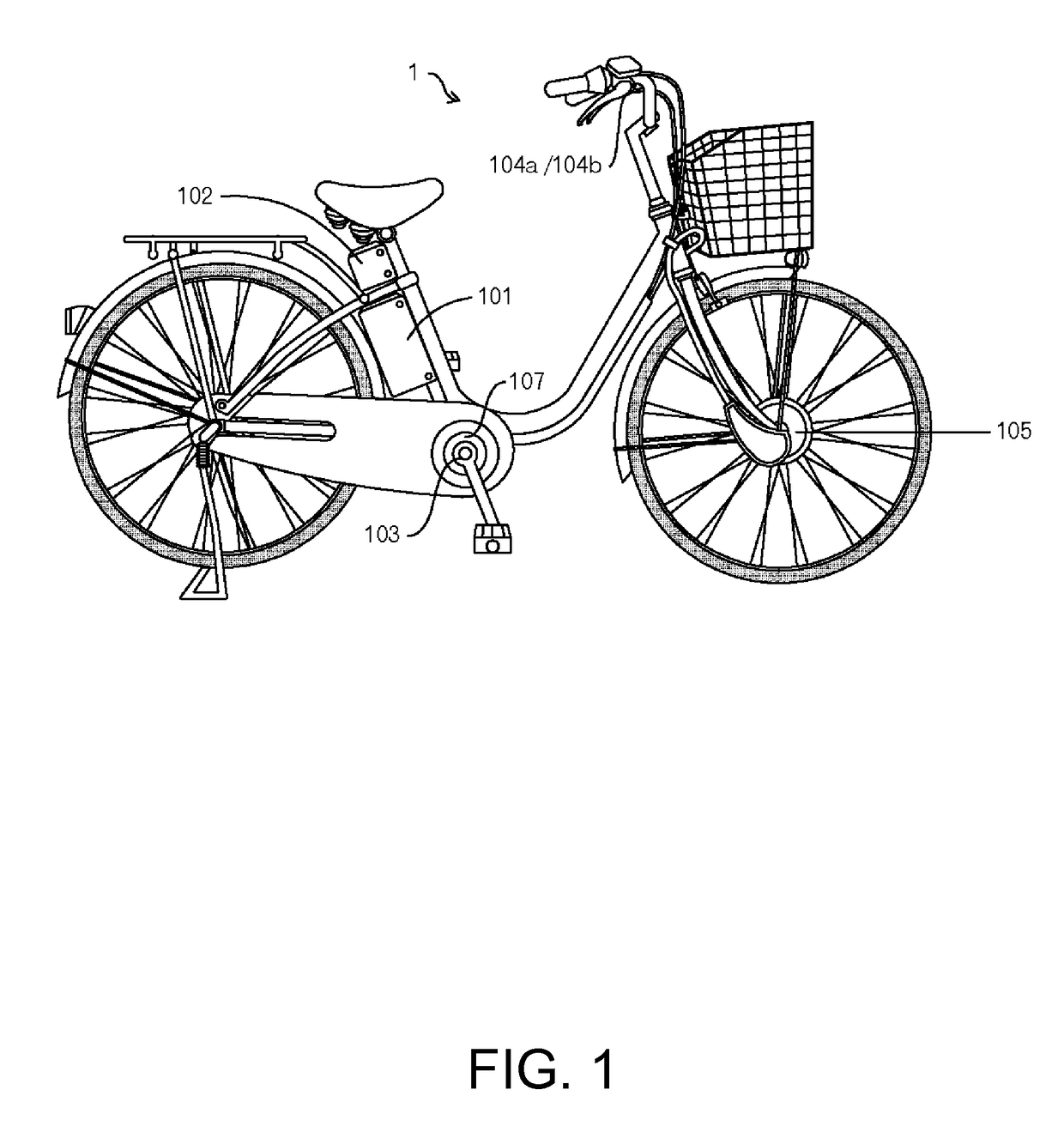
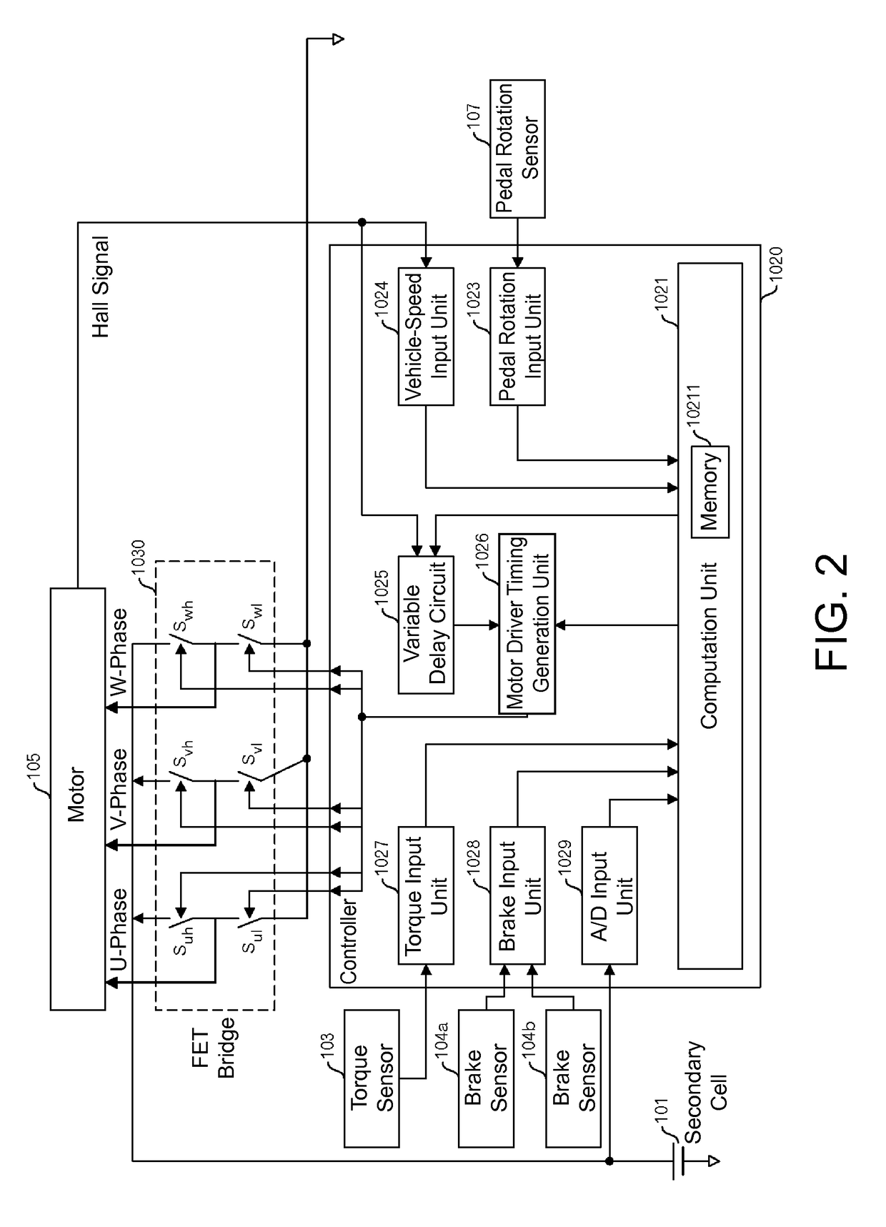
[0039]FIG. 1 is an external view of one example of a bicycle with a motor attached thereto of the present embodiment, which is an electric power-assisted vehicle. This motor-assisted bicycle 1 is equipped with a motor drive controller. The motor drive controller has a secondary cell 101, a controller for driving a motor 102, a torque sensor 103, brake sensors 104a and 104b, a motor 105, and a pedal rotation sensor 107. Although not shown in FIG. 1, the motor drive controller is sometimes provided with buttons or the like for enabling an exercise mode.

[0040]The secondary cell 101 is a lithium ion secondary cell with a maximum supply voltage (the voltage when fully charged) of 24V, for example. Other types of batteries, however, such as a lithium ion polymer secondary cell, a nickel-hydrogen storage battery, or the like may be used, for example.

[0041]The torque sensor 103 is provided on the wheel that is installed on the crankshaft, and detects the pedal force of the rider and outputs...

embodiment 2

[0061]In Embodiment 1, an example was shown in which only ON and OFF are possible for regenerative operation, but in the present embodiment, it is possible to configure a regenerative control amount that is more in accordance with the intentions of the rider.

[0062]Specifically, control coefficients, such as shown in FIG. 9, are configured. Namely, in the example shown in FIG. 9, the horizontal axis represents the backwards pedal rotation accumulation amount (phase angle) θ, and the vertical axis represents the control coefficient. In this manner, until a set value θ1, the control coefficient increases proportionally to the increase in the backwards pedal rotation accumulation amount. The slope during this time is (control coefficient maximum value) / θ1. When the backwards pedal rotation accumulation amount reaches θ1 and the control coefficient arrives at the maximum value, the control coefficient is maintained at the maximum value even if the backwards pedal rotation accumulation am...


PUM


Abstract

In one aspect, a controller for driving a motor of the present invention includes a driving control unit that controls driving of a motor, and a regenerative control unit that instructs the driving control unit to start regeneration when a signal from a pedal rotation sensor that detects a rotation direction of a pedal indicates that the rotation direction of the pedal is backwards, the regenerative control unit controlling an amount of the regeneration in accordance with a rotation amount of the pedal while the rotation direction of the pedal is backwards, the rotation amount being obtained by the pedal rotation sensor.

Description

BACKGROUND OF THE INVENTION[0001]Technical Field[0002]The present invention relates to regenerative control technology for a motor.[0003]Background Art[0004]Electric power-assisted vehicles, such as electric bicycles driven by battery power, use sensors provided on brake levers. These sensors respond to the usage of the brakes by the rider in order to enable regenerative operation of the motor, which stores the kinetic energy of the vehicle into the battery and improves the travel distance of the vehicle.[0005]Bicycles, unlike automobiles and motorcycles, do not have engine brakes, resulting in a sense of danger for the rider when descending long downward slopes at a high speed. Therefore, the speed must be controlled through operation of the brakes. There are problems, however, such as this kind of braking operation being bothersome for the rider, and hand fatigue occurring due to prolonged operation of the brakes.[0006]Meanwhile, it is possible to control regenerative braking thro...

Claims


Application Information

Patent Timeline
Patent Type & Authority Patents(United States)
IPC IPC(8): B62M6/00B60L7/10B62M6/45
CPCB60L7/10B62M6/45B60L7/18B60L15/2018B60L15/30B60L2200/12Y02T10/72B60L50/20Y02T10/64
Inventor HOSAKA, YASUOASANUMA, KAZUOKAWAGOE, KUNIAKISHIMIZU, SATORU
Owner TAIYO YUDEN KK
Learn More