
Vacuum apparatus and vacuum processing method

a vacuum apparatus and vacuum processing technology, applied in vacuum evaporation coatings, diaphragms, chemical vapor deposition coatings, etc., can solve the problems of wasting a lot of time, and achieving the effect of shortening the time for regenerating plasma and facilitating the regenerating of plasma

Active Publication Date: 2007-04-17
ULVAC INC
View PDF8 Cites 2 Cited by
  • Summary
  • Abstract
  • Description
  • Claims
  • Application Information

AI Technical Summary

Benefits of technology

[0020]The present invention is to solve the foregoing problem of the prior art; and an object of the present invention is to provide a matching box which can control the impedance with high speed. Another object of the present invention is to also provide a vacuum apparatus using the matching box to shorten time for regenerating plasma. Another object of the present invention is to provide a vacuum processing method which can regenerate the plasma with ease.
[0034]According to the above-discussed present invention, it is possible to electrically control the impedance of a variable inductance element included in the matching box. Thus, since the impedance of the matching box is rapidly variable as compared to mechanical control, it is possible to shorten time for regenerating plasma.
[0035]In regenerating plasma, since electrons emitted from an electron generator are attracted into an ionization chamber, the electrons becomes the source of plasma regeneration so that it is possible to regenerate the plasma with ease.

Problems solved by technology

Accordingly, there is the disadvantage that it takes several hundreds milliseconds to several seconds to match the impedance of the matching box 102 to that inside the RF ion gun 112.
Accordingly, even if the RF ion gun 112 is restarted, the produced filter becomes defective because the film deposition is stopped for several seconds or more.
In other words, a significant problem occurs when an accurate film forming process of several tens of hours ends in failure because of only one time of discharge interruption of several seconds.

Method used


Image

  • Vacuum apparatus and vacuum processing method
  • Vacuum apparatus and vacuum processing method
  • Vacuum apparatus and vacuum processing method

Examples


Embodiment Construction

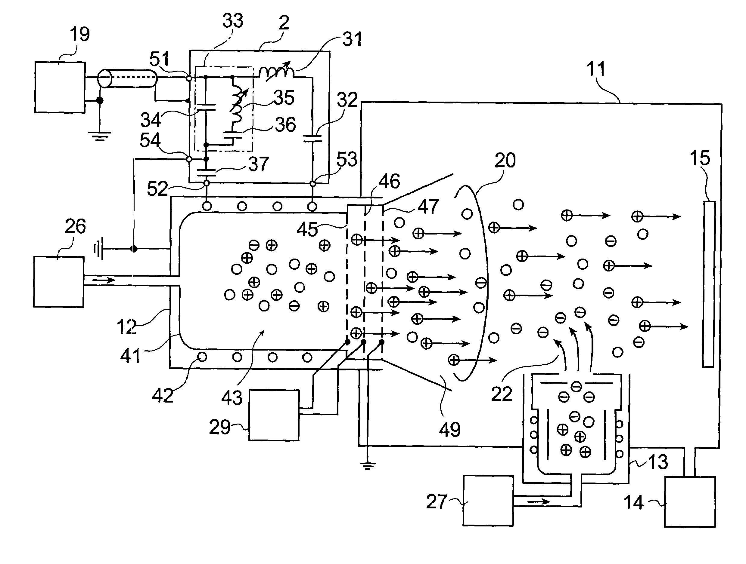
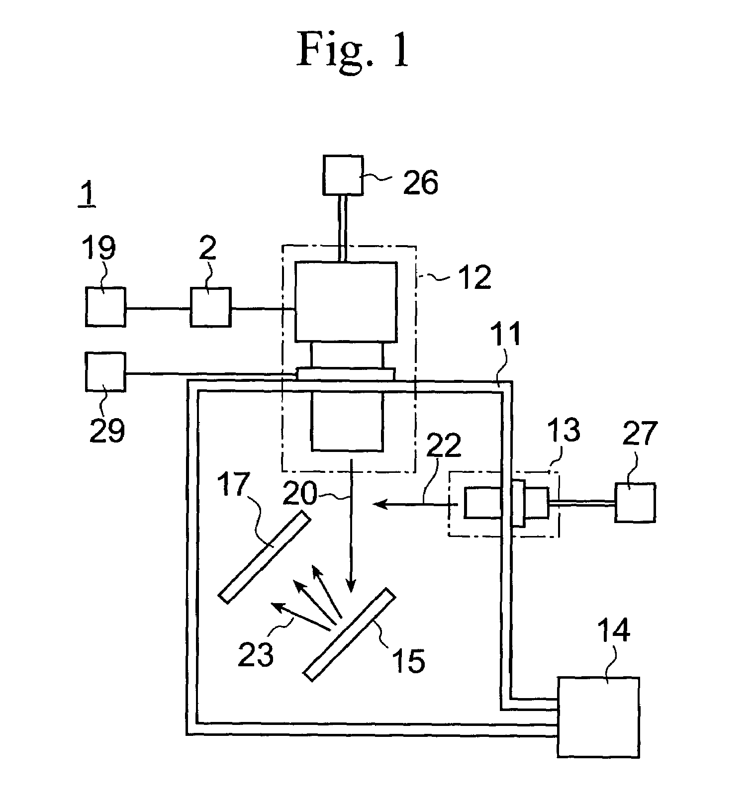
[0042]FIG. 1 shows one embodiment of a vacuum apparatus according to the present invention, wherein the vacuum apparatus has a vacuum chamber 11. A plasma generator 12 and an electron generator (neutralizer) 13 are provided on the wall of the vacuum chamber 11. A RF source 19 and a DC voltage supply 29 are disposed outside of the vacuum chamber 11. The RF source 19 output high frequency AC power.

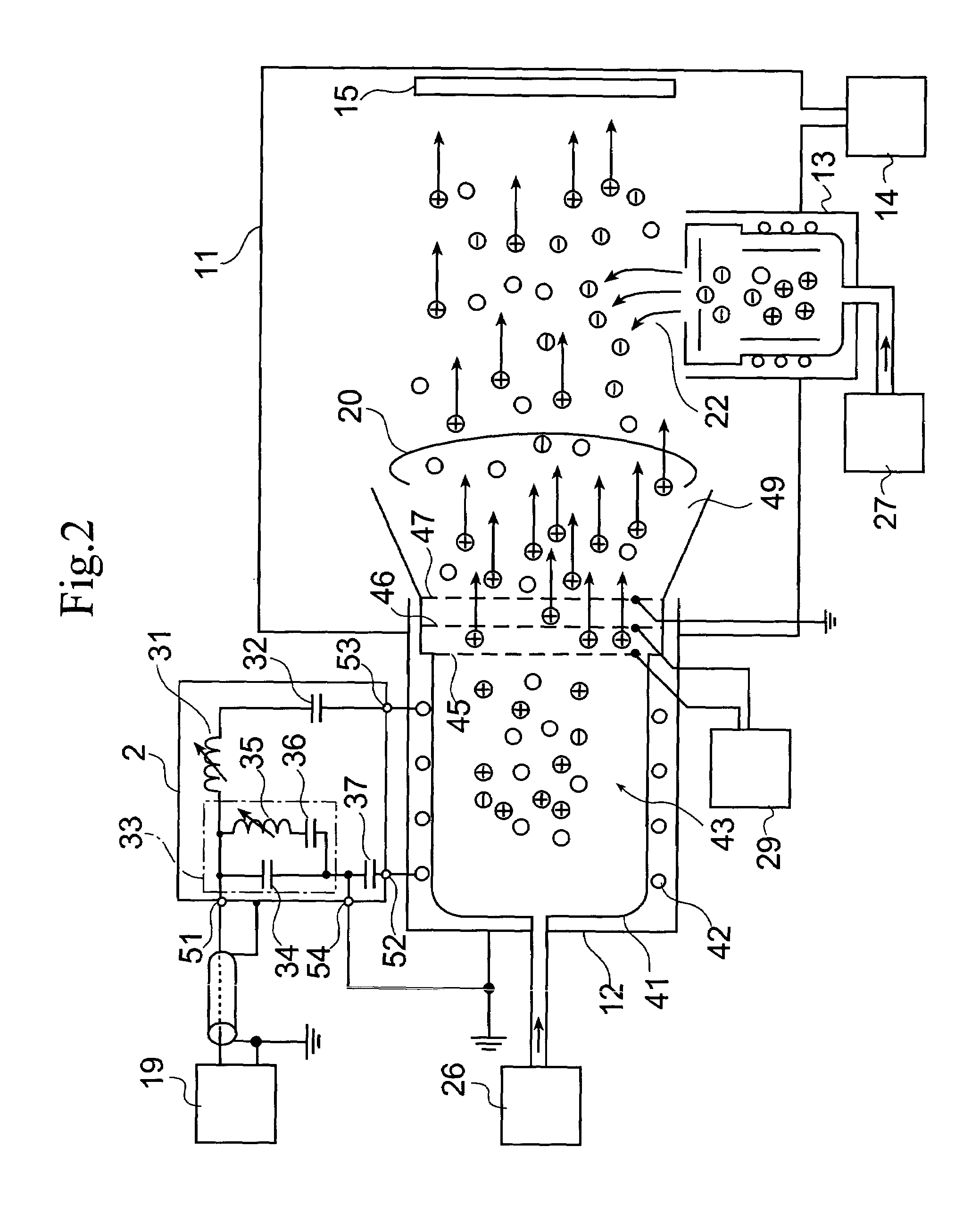
[0043]FIG. 2 shows the inside of the plasma generator 12 and a matching box 2.

[0044]The matching box 2 has an input terminal 51, a ground terminal 54, a ground side output terminal 52 and a high voltage side output terminal 53.

[0045]The ground terminal 54 of the matching box 2 is grounded, and the ground side output terminal 53 is connected to the ground terminal 54 via an internal circuit of the matching box 2 described later.

[0046]The input terminal 51 of the matching box 2 is connected to the RF source 19 with a shielding wire. When the RF source 19 outputs RF power, the internal circuit ...


PUM

PropertyMeasurementUnit
voltagesaaaaaaaaaa
voltagesaaaaaaaaaa
voltageaaaaaaaaaa

Abstract

A vacuum apparatus which can easily regenerate plasma is provided. A matching box used in the vacuum apparatus can vary the impedance thereof by varying the magnitudes of the inductance of variable inductance elements. Controlling the magnitude of direct current makes it possible to control the magnitudes of inductance of the variable inductance elements so that it is possible to carry out matching operation at high speed.

Description

BACKGROUND OF THE INVENTION[0001]1. Field of the Invention[0002]The present invention relates to a vacuum apparatus, and especially the present invention relates to a vacuum apparatus using an ion gun.[0003]2. Description of the Prior Art[0004]In a film deposition process using an ion gun, there are some representative film deposition methods such as an ion beam sputtering method in which ion beam generated by an ion source (plasma) collides against a target and sputtered particles from a target surface form a film, and an ion assist evaporation method in which thin film material is vaporized by an electron gun and the ion gun assists to form a film, or the like. The ion gun is also used in an ion beam etching method, in which etching is carried out with the use of an ion beam, in addition to the film deposition process.[0005]In these processes, there are, for example, three types of ion guns that are used, which are classified according to a method for generating plasma therein. Th...

Claims


Application Information

Patent Timeline
Patent Type & Authority Patents(United States)
IPC IPC(8): C23C14/34C23C16/00H01J7/24C23C14/40G21K1/00C23C14/46G21K5/04H01J27/16H01J37/08H01J37/32H01L21/3065H03H7/40H05H1/36H05H1/46
CPCH01F29/14H01J37/08H01J37/24H05H1/46H01J37/32183H01J37/32357H01J37/32082H01J2237/31H05H1/36
Inventor YAJIMA, TAROAKAISHI, MINORUHORISHITA, YOSHIKUNI
Owner ULVAC INC
Learn More