Mechanical — pharmaceutical system for opening obstructed bodily vessels

a technology of bodily vessels and mechanical parts, applied in the field of mechanical — pharmaceutical systems for opening obstructed bodily vessels, can solve the problems of forcing patients to undergo a more formidable bypass surgery, and achieve the effect of reducing the likelihood of releasing particles and ensuring aspiration

Active Publication Date: 2018-03-06
SHIBER SAMUEL
View PDF60 Cites 3 Cited by
  • Summary
  • Abstract
  • Description
  • Claims
  • Application Information

AI Technical Summary

Benefits of technology

[0008]By way of comparison, an embodiment of the present invention has an asymmetric narrow tip with sides that are designed to bluntly impact the obstruction to break the obstruction mechanically. The narrow tip also defines passages that deliver cooling / lubricating fluid and drugs to the impact site. As the mechanical impacting increases the surface area of the obstruction material the pharmaceutical action is accelerated so that the combined mechanical and pharmaceutical actions synergistically breakdown the obstruction to particles quickly. The same passages further allow the aspiration of fluid laden with particles.
[0009]The embodiment comprises a motor-driven flexible hollow shaft whose distal portion is preferably made of a spiraled wire and a tip affixed to its distal end. The flexible hollow shaft is rotatably disposed in a flexible tube and a fluid channel is defined between an internal diameter of the flexible tube and an external diameter of the hollow shaft. The distal portion of the flexible hollow shaft extends out of and is free to move radially relative to the tube, enabling the fluid channel to ingest particles which are smaller than a difference between the internal and external diameters. Relative motion between the radially moving and rotating flexible hollow shaft and the flexible tube eases movement of the particles through the fluid channel and impedes the particles from clogging the fluid channel. A tip made of a hard material, such as stainless steel having a narrowed cross section (as compared to a round cross section), is affixed to a distal end of the hollow shaft. The tip has a rounded atraumatic (i.e., less likely to injure a wall of the vessel) distal end which defines a bore adapted to fit over a guidewire and the flexible hollow shaft and the tip are rotatable and slideable over the guidewire. The tip, which is extended out of a distal end of the flexible tube to enhance its engagement with the obstruction material, has a first and second sides. The first side is adapted to bluntly impact the obstruction material when the tip rotates in a first direction and vice versa. The tip also has a base and an opposing smooth crown that is offset away from a longitudinal axis of the flexible hollow shaft further than the base is offset away from the longitudinal axis, enlarging the area that the tip can sweep when rotating in a larger vessel.
[0010]A distance between the sides is smaller than the distance between the crown and the base, leaving open aspiration passageways along the sides even when the tip is a small vessel or when it is tunneling through a hard obstruction. The passages allow fluid (e.g., saline, thrombolytic and other drugs as well as blood) to irrigate and lubricate the impact-site and bring the drugs in contact with the obstruction's new surfaces as soon as they are created by the rotating tip in order to combine the chemical effect with the tip's mechanical effect. The maintained fluid supply through the passages also prevents the impact-site from becoming dry and overheated by the mechanical action of the rotating tip. The passages also carry the particles from the impact site as well as the area surrounding the distal end of the rotating tip, as they are aspirated into the tube.
[0011]Total occlusions often prevent advancement of a guidewire and thereby prevent the delivery of percutaneous trans-catheter treatment, forcing a patient to undergo a more formidable bypass surgery. With the present invention, upon encountering a total obstruction that cannot be crossed with the guidewire, the rotary catheter can be advanced to the obstruction and the guidewire can be withdrawn proximally past the tip, adapting the system to cross a total occlusion. As the tip is rotated, it's smooth crown atraumatically slides against the vessel's wall and displaces the distal end of the tip away from the wall, directing the tip to tunnel through the obstruction. Once the obstruction is crossed, the guidewire can be advanced distally past the tip to provide guidance and support to the rotary catheter.
[0012]The rotary catheter can be inserted into the vessel directly, e.g., when access to a vessel is gained surgically, or through the skin via an introducer. The introducer can also be used to inject fluids, such as saline, with drugs and radiopaque contrast agent into the vessel, which, together with blood, keeps the obstruction particles suspended so that they can be readily aspirated. An optional guiding catheter can be used when the rotary catheter has to be guided further into the vessel. The guiding catheter can incorporate a proximal embolic barrier for temporarily blocking flow through the vessel, while the rotary catheter macerates and aspirates the obstruction material, thereby reducing the likelihood of releasing particles and drugs downstream. A distal embolic protection device can also be employed for the same purpose and, when the rotary catheter is used in a limb, an external pressure cuff can be utilized to temporarily stop circulation in the affected limb.
[0013]The flexible hollow shaft that is disposed in the flexible tube deters the flexible tube from kinking (i.e., diametrically collapsing) and prevents the flexible hollow shaft and tube from being sharply bent at the point in which they are connected to the housing. Their radii of bending is limited by a radius of curvature of a wall of a depression defined by the surrounding housing. The rotary catheter can be manufactured in varying lengths and diameters to reach and treat different anatomical locations and different forms of obstructions, as well as to suit users' preferences.

Problems solved by technology

Total occlusions often prevent advancement of a guidewire and thereby prevent the delivery of percutaneous trans-catheter treatment, forcing a patient to undergo a more formidable bypass surgery.

Method used


Image

  • Mechanical — pharmaceutical system for opening obstructed bodily vessels
  • Mechanical — pharmaceutical system for opening obstructed bodily vessels
  • Mechanical — pharmaceutical system for opening obstructed bodily vessels

Examples


Embodiment Construction

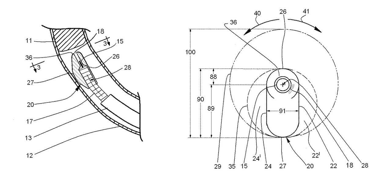
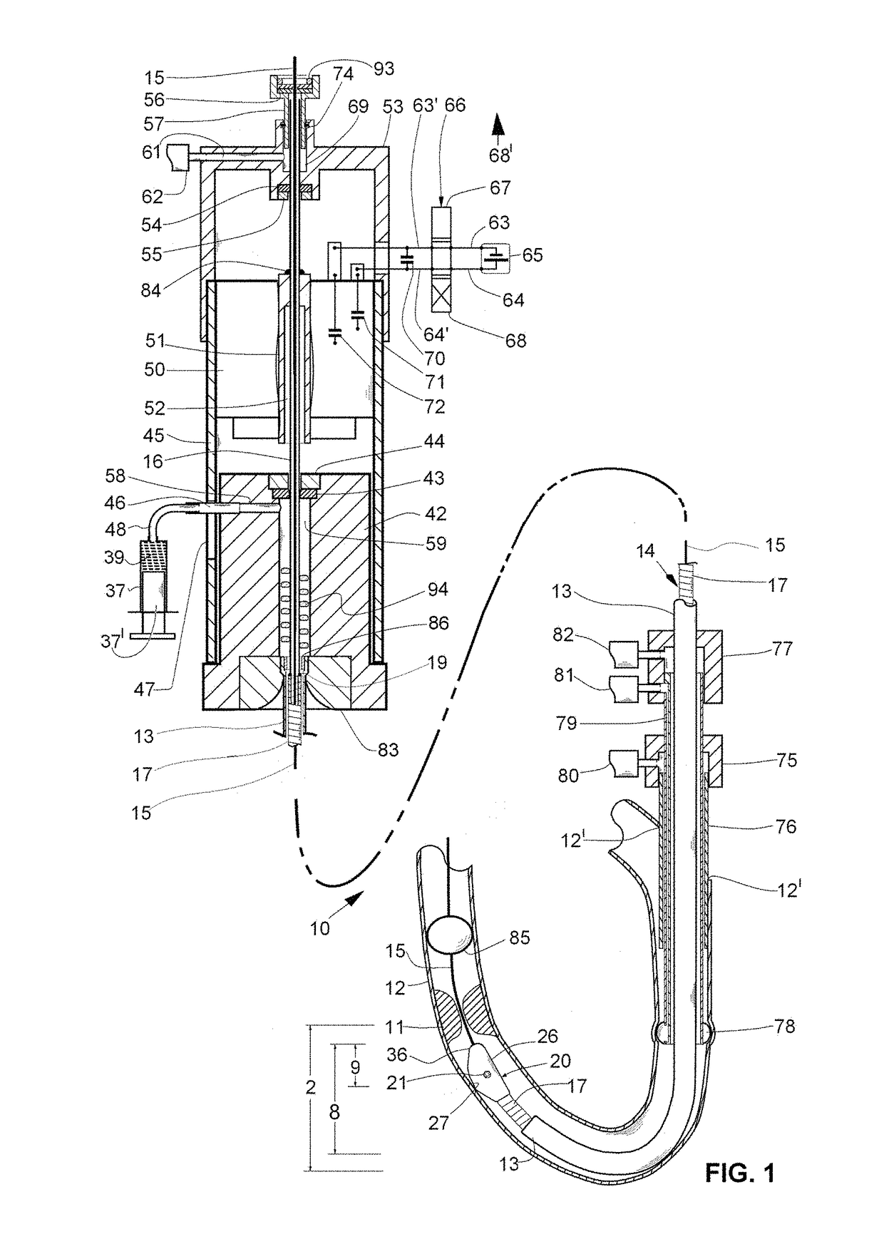
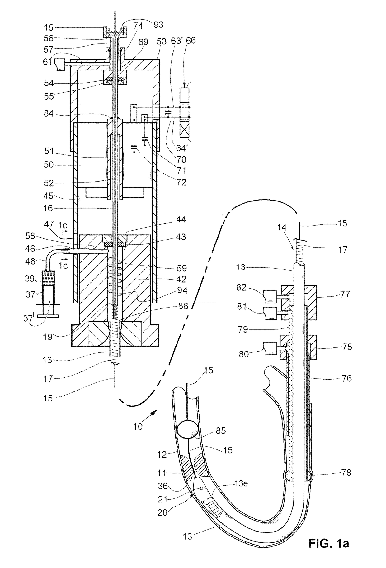
[0043]FIG. 1 shows a motorized rotary catheter 10, according to the present invention, for opening an obstruction 11 (e.g., blood clot; atheroma) in a bodily vessel 12 (e.g., a blood vessel).

[0044]The rotary catheter 10 comprises a motor-driven flexible hollow shaft 14, rotatably disposed in a flexible tube 13 that is preferably made of thin plastic material. A proximal portion 16 of the flexible hollow shaft is preferably a thin-walled tube and a distal portion of the flexible hollow shaft 17 is preferably made of a spiraled wire. The wire that is used to wind the spiraled wire preferably has a flattened cross-section (such a cross section can be obtained by taking a standard round wire and running it between rollers that squeeze and flatten it, please note FIGS. 4-6.). The flexible hollow shaft portions 16 and 17 are preferably made of metal (e.g., stainless steel; Nitinol) and are connected together, for example, by a circumferential weld 19 (please note FIG. 1) or by two circumf...


PUM


Abstract

A rotary catheter comprising a motor-driven flexible shaft rotatably disposed in a flexible tube having a fluid channel between them, a distal portion of the flexible shaft extending out of the tube and being free to move radially relative to the tube enabling the fluid channel to ingest large particles eased by motions between the rotating flexible shaft and the flexible tube, and pump means containing a thrombolytic drug connected to the fluid channel for infusing the drug through the fluid channel to the obstruction. An asymmetrical tip that is affixed to a distal end of the shaft has a substantially narrower cross section than its effective diameter so that fluid can flow alongside the tip and reach the area that the tip impacts the obstruction with the side of the tip and the tube aspirates fluid and the resulting particles into the channel.

Description

CROSS REFERENCE TO RELATED APPLICATIONS[0001]Priority is claimed based on:[0002]U.S. patent application Ser. No. 13 / 695,232 by Shiber, entitled “ROTARY CATHETER FOR REMOVING OBSTRUCTIONS FROM BODILY VESSELS”, filed on Jan. 8, 2013, which claims priority from Pat. Appl. PCT / US2011 / 031197 filed on Apr. 5, 2011 by Shiber, and entitled “ROTARY CATHETER FOR REMOVING OBSTRUCTIONS FROM BODILY VESSELS”, which further claims priority from U.S. Provisional Pat. Appl. Ser. No. 61 / 343,796, filed on May 4, 2010 by Shiber and entitled “THROMBECTOMY AND ATHERECTOMY CATHETER” and U.S. Provisional Pat. Appl. 61 / 461,263 filed on Jan. 14, 2011 by Shiber and entitled “CATHETER FOR THROMBECTOMY AND ATHERECTOMY”; and[0003]U.S. patent application Ser. No. 14 / 238,983, filed on Feb. 14, 2014, by Shiber, entitled “ADAPTIVE ROTARY CATHETER FOR OPENING OBSTRUCTED BLOOD VESSELS”, which claims priority from Pat. Appl. PCT / US2012 / 050759 filed on Aug. 14, 2012 by Shiber, and entitled “ADAPTIVE ROTARY CATHETER FOR ...

Claims


Application Information

Patent Timeline
Patent Type & Authority Patents(United States)
IPC IPC(8): A61B17/22A61B17/3207A61B17/32
CPCA61B17/320758A61B2217/007A61B2017/320766A61B2017/320004
Inventor SHIBER, SAMUEL
Owner SHIBER SAMUEL
Why Eureka
Try Eureka