Method for detecting the foam boundary and a respectively equipped apparatus

a foam boundary and equipped technology, applied in the direction of liquid/fluent solid measurement, engine lubrication, withdrawing sample devices, etc., can solve the problem of unsatisfactory reliability of liquid surface recognition with the known methods, and achieve the effect of high reliability and precise manner

Active Publication Date: 2018-03-06
TECAN TRADING AG
View PDF7 Cites 0 Cited by
  • Summary
  • Abstract
  • Description
  • Claims
  • Application Information

AI Technical Summary

Benefits of technology

[0029]The most important advantage of the invention is that during the feed motion of a probe (e.g. in form of a pipette or needle) a foam boundary can be detected in a highly reliable and precise manner. It can thus be ensured that a respectively equipped apparatus for example supplies correct data and / or that an automated process can be carried out without the likelihood that unforeseeable events occur or actions are carried out as a result of erroneous detection which are not adequate to the situation.
[0030]It is a further advantage of the invention that it is possible to distinguish between foam or liquid contacting, wherein both the detection of a foam boundary and also the detection of the liquid boundary occur according to measuring approaches which are compatible with respect to metrology and circuitry.

Problems solved by technology

The reliability of the recognition of the liquid surface with the known methods is unsatisfactory in a number of cases, especially in the case of liquids which are susceptible to the formation of foam.

Method used


Image

  • Method for detecting the foam boundary and a respectively equipped apparatus
  • Method for detecting the foam boundary and a respectively equipped apparatus
  • Method for detecting the foam boundary and a respectively equipped apparatus

Examples


Embodiment Construction

[0041]Advantageous embodiments of the invention are described below, wherein said embodiments are provided as examples. They comprise both different formations of the overall invention, but also assemblies and individual parts of the invention. The described assemblies and individual parts of the various embodiments can principally be combined with each other, or the assemblies and individual parts of individual embodiments can be replaced by the assemblies and individual parts of other embodiments. The combinations formed in this case can lead to minor adjustments that are known to every person skilled in the art and will therefore not be described in closer detail, e.g. in order to enable an interaction or mutual engagement of the assemblies and individual parts.

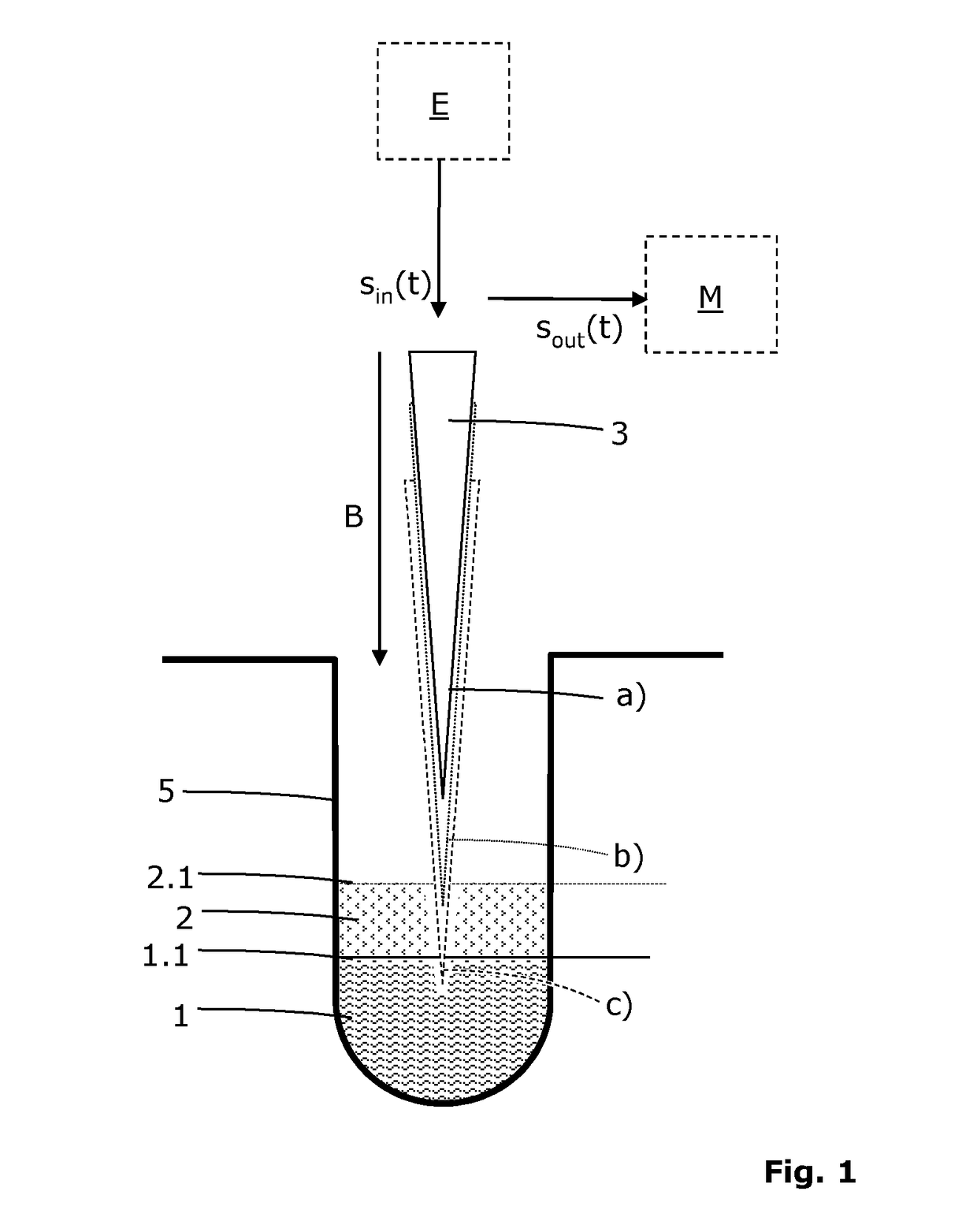
[0042]The term phase boundary is used for boundaries between two or more media which have different dielectric constants. Gas-foam phase boundaries 2.1, foam-liquid phase boundaries 1.1, such as indicated in FIG. 1, and ga...


PUM

PropertyMeasurementUnit
capacitanceaaaaaaaaaa

Abstract

A capacitively operating apparatus (100) has a container, a probe (3) movable into and / or out of the container, an input signal generator connectable to the probe (3) to provide an input signal (sin(t)) which produces at least one output signal (sout(t) in the probe (3), and a measuring apparatus (M) connectable to the probe (3) to tap the output signal (sout(t)) from the probe (3), and wherein the probe (3) is periodically chargeable and dischargeable, the output signal (sout(t)) corresponds to the time progression of a charging / discharging curve which is produced by the periodic charging and discharging of the probe (3). The apparatus (100) also includes a circuit module (10, 11) with two comparators for providing a first comparator output signal (PWM1) and a second comparator output signal (PWM2) from the output signal (sout(t)) and to correlate them with one another.

Description

[0001]The invention relates to a method for detecting a foam boundary in a container. The invention also relates to a respectively equipped apparatus.BACKGROUND OF THE INVENTION[0002]There are numerous laboratory systems and medical as well as pharmaceutical appliances which require precise pipetting operations in order to obtain satisfactory analytic precision. It is necessary for this purpose to precisely define the filling level in test tubes, titre plates and other liquid containers. There are also applications which are concerned with the detection of foam-liquid phase boundaries and gas-foam phase boundaries. The term phase boundary shall be used below both for transitions between gaseous and liquid media (gas-liquid phase boundary), for gas-foam phase boundaries, and also for transitions between different liquid media (foam-liquid phase boundary).[0003]Such a determination of the phase boundary is particularly relevant concerning the automation of measurement or test sequence...

Claims


Application Information

Patent Timeline
Patent Type & Authority Patents(United States)
IPC IPC(8): G01R27/08G01N1/10G01N35/10G01N27/22G01F23/00G01F23/26
CPCG01N27/22G01F23/0069G01F23/265G01N1/10G01N35/1011G01F23/266G01N2035/1018G01F23/802
Inventor SCHOENI, MARKUSOTT, PHILIPPKAMM, LARSZBINDEN, PAUL
Owner TECAN TRADING AG
Why Eureka
Try Eureka