Electronic ignition circuit and method for use

Active Publication Date: 2018-03-13
DYNAENERGETICS
View PDF22 Cites 14 Cited by
  • Summary
  • Abstract
  • Description
  • Claims
  • Application Information

AI Technical Summary

Benefits of technology

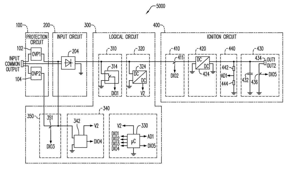
[0006]In some embodiments, the present disclosure describes an electronic ignition circuit

Problems solved by technology

While this method improves mechanical stabilization of the well, unfortunately, it also isolates inner

Method used


Image

  • Electronic ignition circuit and method for use
  • Electronic ignition circuit and method for use
  • Electronic ignition circuit and method for use

Examples


Example

[0021]The following description and drawings are illustrative and are not to be construed as limiting. Numerous specific details are described to provide a thorough understanding of the disclosure. However, in certain instances, well-known or conventional details are not described in order to avoid obscuring the description.

[0022]Reference in this specification to “one embodiment,”“an embodiment” or the like means that a particular feature, structure, characteristic, advantage or benefit described in connection with the embodiment may be included in at least one embodiment of the disclosure, but may not be exhibited by other embodiments. The appearances of the phrase “in one embodiment” in various places in the specification are not necessarily all referring to the same embodiment, nor are separate or alternative embodiments mutually exclusive of other embodiments. Similarly, various requirements are described which may be requirements for some embodiments but not for other embodime...


PUM


Abstract

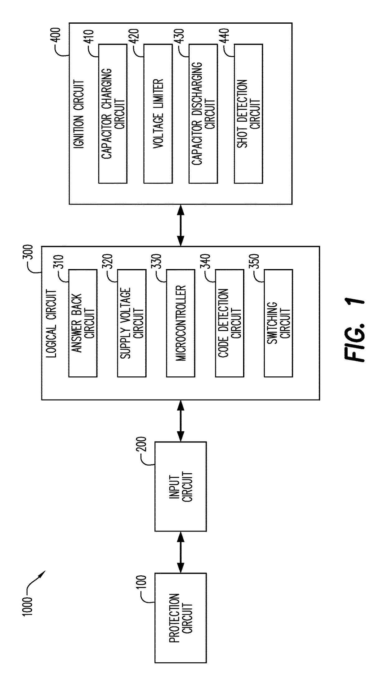
The present disclosure describes an electronic ignition circuit (“EIC”) for controlling at least one detonator. The EIC may include a protection circuit, an input circuit coupled to the protection circuit, a logical circuit electrically coupled to the input circuit, and an ignition circuit electrically coupled to the logical circuit. The protection circuit may include at least one of a fuse, a circuit breaker and an automatic switch. The logical circuit may include an answer back circuit, and a switching circuit adapted to switch to the next detonator or igniter. The ignition circuit may include a capacitor charging circuit, a capacitor discharge circuit to discharge a firing capacitor through a fuse head, and a shot detection circuit adapted to measure a voltage across the firing capacitor before discharging through the fuse head and to measure a voltage after discharging through the fuse head.

Description

CROSS-REFERENCE TO RELATED APPLICATIONS[0001]This application claims the benefit of U.S. Provisional Application No. 62 / 454,841, filed Feb. 5, 2017, which is incorporated herein by reference in its entirety.FIELD[0002]The present disclosure relates generally to electronic ignition circuits (“EIC”) for controlling and inducing the ignition of explosive substances. More specifically, an EIC controls an igniter / detonator in a well perforation system containing an explosive or pyrotechnic substance used in oil and natural gas wells, are described herein.BACKGROUND[0003]Many different commercial activities employ one or more explosive, pyrotechnic and gas-producing substances (herein, “explosive substances”) to achieve a variety of engineering and ultimately commercial objectives. For example, explosive substances are used in the oil and natural gas industries to enhance production in wells. Once a promising location has been identified, and the necessary rights secured, the creation of ...

Claims


Application Information

Patent Timeline
IPC IPC(8): F42D1/05H02H3/20F42C15/40
CPCF42D1/05H02H3/202F42C15/40F42B3/12F42C15/42F42D1/055F42B3/122
Inventor ZEMLA, ANDREAS ROBERTTHIELTGES, SASCHAGRAZIOLA, FRANK
Owner DYNAENERGETICS
Why Eureka
Try Eureka