
Linkage rod including limited-displacement flexible mechanism

a flexible mechanism and linkage rod technology, applied in the direction of machine supports, instruments, etc., can solve the problems of difficult to prevent the breakage of machinery under heavy load or severe environments, the existing techniques cannot achieve a light-weight, simple-to-manufactured hexapod with high precision, and the difficulty of miniaturization and weight reduction. , to achieve the effect of simple production and easy reduction in weight and siz

Active Publication Date: 2018-03-20
NEC CORP
View PDF38 Cites 2 Cited by
  • Summary
  • Abstract
  • Description
  • Claims
  • Application Information

AI Technical Summary

Benefits of technology

The present invention provides a linkage rod with a flexible mechanism that allows for easy weight reduction and size, while maintaining structural strength. The production process is simple and cost-effective.

Problems solved by technology

However, in the case of a supporting rod with high rigidity and strength so as to achieve precise positioning, it is necessary to use a plurality of parts to assemble the machinery, resulting in difficulty in miniaturization and weight reduction.
On the other hand, if in the case where the flexible strips are employed for a linkage rod as the above-mentioned mounting assembly, it is difficult to prevent the machinery from breakage under heavy load or severe environments.
Accordingly, the existing techniques cannot achieve a light-weight, miniaturized and simply-manufactured hexapod with high precision.

Method used


Image

  • Linkage rod including limited-displacement flexible mechanism
  • Linkage rod including limited-displacement flexible mechanism
  • Linkage rod including limited-displacement flexible mechanism

Examples


first exemplary embodiment

3. First Exemplary Embodiment

3.1) Structure

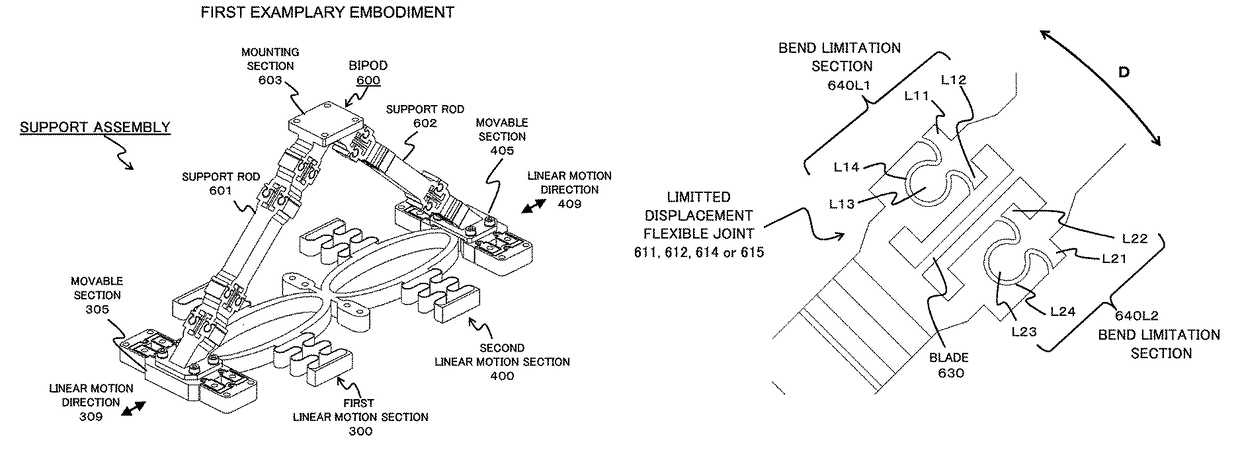
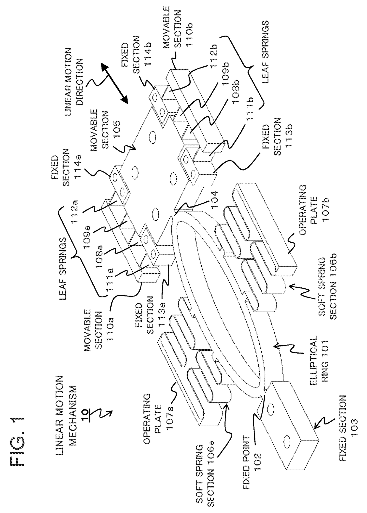
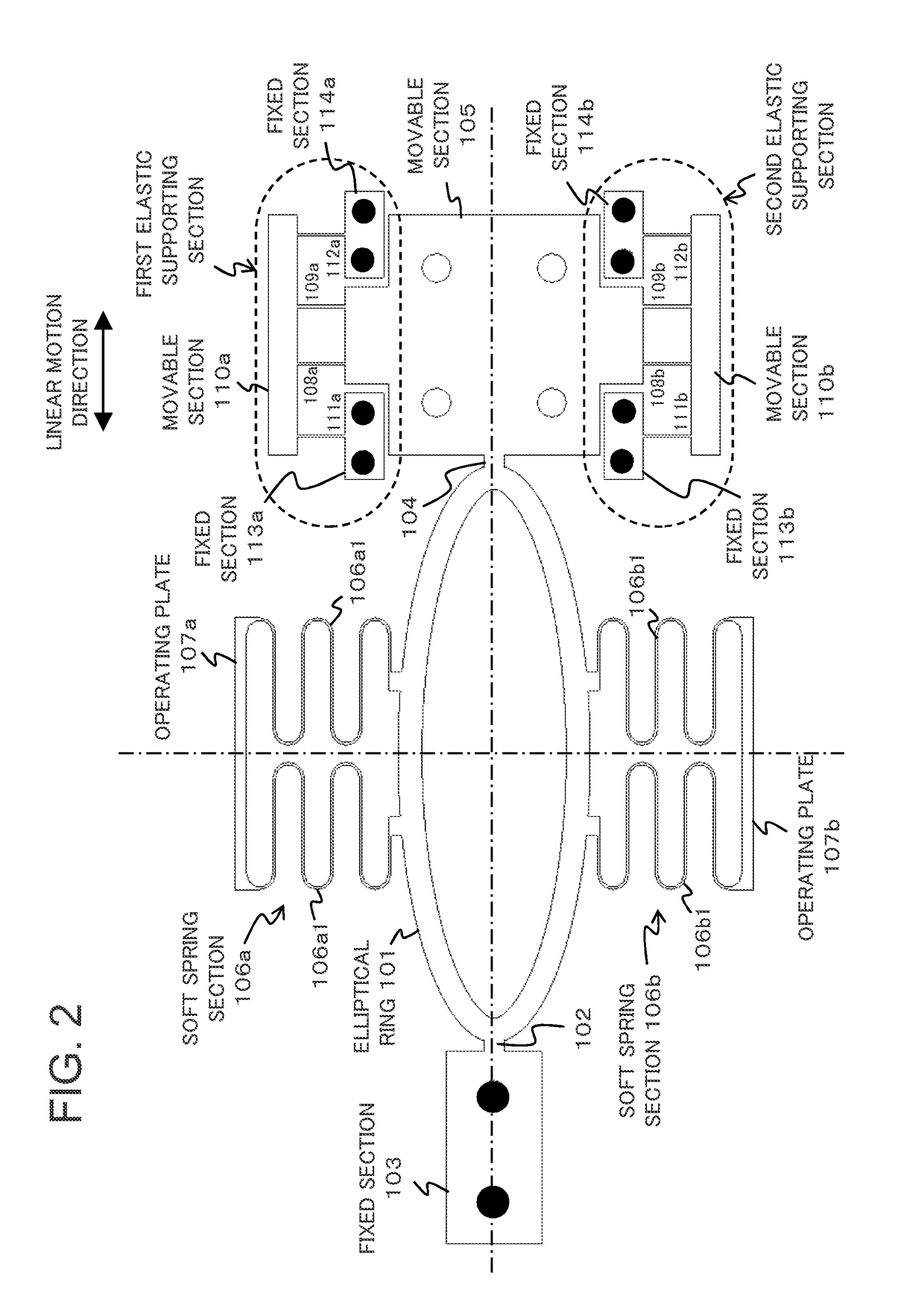
[0058]Referring to FIG. 8, a support assembly using a bipod composed of two linkage rods according to a first exemplary embodiment of the present invention is composed of a bipod 600 and the linear motion mechanism 20 as described above. The bipod 600 has two support rods 601 and 602, one ends of which are connected at a top provided with a support section 603 to form an upside-down V-shaped bipod. The other ends of the support rods 601 and 602 are fixed to the movable section 305 of the first linear motion section 300 and the movable section 405 of the second linear motion section 400, respectively. The support rods 601 and 602 have the same structure. Hereinafter, the structure of the support rod 601 shown in FIGS. 9-11 will be described as an example.

3.2) Bipod

[0059]Referring to FIGS. 9-11, the support rod 601 is shaped like a leg including a fixed portion 610, two limited-displacement flexible joints 611 and 612, a relatively rigid rod ...

second exemplary embodiment

4. Second Exemplary Embodiment

4.1) Structure

[0069]Referring to FIGS. 17-21, a hexapod arrangement having six degrees of freedom includes a base plate 701, a top plate 702 and three support assemblies A, B and C, each of which is composed of the bipod (600A, 600B, 600C) and the linear motion mechanism (20A, 20B and 20C) as shown in FIG. 8. The support assemblies A, B and C are fixed and arranged on the base plate 701 with regular-triangular configuration as typically shown in FIG. 20. The top plate 702 is fixed to the support sections of the bipods 600A, 600B and 600C. Accordingly, the top plate 702 is supported by three position-adjustable points.

[0070]As an example, the base plate 701 is circular and the top plate 702 is star-shaped. The top plate 702 may be formed of three legs 702A, 702B and 702C joined at a center point with the angle between any two adjacent legs being 120 degrees. The three legs 702A, 702B and 702C are supported respectively by the support assemblies A, B and ...


PUM


Abstract

A linkage rod including a limited-displacement flexible mechanism has structural robustness and allows easy reduction in weight and size, simple production and easy operation. The linkage rod including at least one limited-displacement flexible mechanism, wherein the limited-displacement flexible mechanism comprises at least one limited-displacement flexible joint which comprises: a flexible member; and at least one bend limitation section which is arranged in parallel with the flexible member so that the bend limitation section limits a bend of the flexible member.

Description

BACKGROUND OF THE INVENTION[0001]1. Field of the Invention[0002]The present invention relates to a limited-displacement flexible mechanism which can be used in a linkage rod or a support arrangement.[0003]2. Description of the Related Art[0004]With the increasing market demand for precision technology, a linear motion actuator providing high precision has become important for machinery requiring precise displacement such as multiple-degree-of-freedom displacement mechanism, micro-manipulator or the like. In most cases, such a linear motion actuator uses an electromechanical or electrohydraulic arrangement which is usually provided for each rod of a six-degree-of-freedom mechanism (so called Hexapod) (see Japanese Patent Unexamined Publication No. JP2013-096574, U.S. Pat. No. 8,978,480 B2). In the hexapod system, each of the six rods is adjustable to precisely position an object in three dimensional space.[0005]A mounting assembly which can correct the position of a device to be supp...

Claims


Application Information

Patent Timeline
Patent Type & Authority Patents(United States)
IPC IPC(8): F16M11/24F16M11/18B25J9/00G02B7/18G02B7/182F16F15/02G02B7/183B25J7/00
CPCF16M11/245B25J7/00B25J9/0042F16F15/02G02B7/1827G02B7/181G02B7/182G02B7/183G02B7/1822F16M11/18F16M11/045F16M11/046F16M11/121F16H21/44G02B7/003G02B7/023G02B7/1805
Inventor KUROSE, MINORUHAMADA, KAZUOKATSUYAMA, YOSHIHIKOKAMIZONO, TAKASHIKOBAYASHI, TAKUROTANIMICHI, NAOTOHAPPY, TSUI
Owner NEC CORP
Learn More