Method of controlling fuel cell system

a fuel cell and system control technology, applied in the direction of battery/fuel cell control arrangement, electrochemical generators, battery/fuel cell propulsion, etc., can solve the problems of not being able to control the fuel cell in this state, not being able to carry out control accompanied with the opening of the main stop valve, and the main stop valve to be changed to closing, etc., to suppress water, avoid or suppress the effect of deterioration of the perform

Active Publication Date: 2018-03-20
TOYOTA JIDOSHA KK
View PDF5 Cites 0 Cited by
  • Summary
  • Abstract
  • Description
  • Claims
  • Application Information

AI Technical Summary

Benefits of technology

[0010]The method of controlling the fuel cell system according to this aspect gives priority to gas filling and changes over the main stop valve from opening to closing. Even when the control accompanied with opening of the main stop valve is performed during vehicle stop, the main stop valve is closed in response to detection of gas filling. As a result, the control accompanied with opening of the main stop valve is not performed parallel to gas filling in an operation stop period of the fuel cell. This contributes to improvement of safety. Even in the case of gas filling with opening a lid provided to cover the filler port of the fuel gas due to some cause such as carelessness or a wrong valve closing operation of a gas filling operator, this configuration causes the main stop valve to be changed over to closing in response to detection of gas filling. This ensures improvement of safety.
[0013](4) in the method of controlling the fuel cell system of the above aspect, the control accompanied with opening of the main stop valve may be a purging process. In the fuel cell, water is produced on the cathode side in the process of electrochemical reaction of hydrogen and oxygen, and the produced water moves to the anode side. The method of controlling the fuel cell system of this aspect performs a purging process as the control accompanied with opening of the main stop valve, on satisfaction of the condition that water (produced water) is likely to be frozen in the fuel cell. The main stop valve is opened to supply the fuel gas to the fuel cell or more specifically to the anode of the fuel cell and discharge water from the anode. This purging process suppresses water from being frozen in the fuel cell and thereby suppresses deterioration of the performance of the fuel cell. In midwinter or in cold district, there is a possibility that water is frozen on the anode during operation stop of the fuel cell. This purging process prevents the electrolyte membrane from being damaged by freezing of water and prevents the gas flow passage from being blocked by frozen water, thus avoiding or suppressing deterioration of the performs nee of the fuel cell.
[0014]As described above, there is a possibility that the operation stop of the fuel cell continues with the lid kept open due to carelessness or the wrong valve closing operation of the gas filling operator. Even in this state, as long as no gas filling is detected, on satisfaction of the condition that water is likely to be frozen in the fuel cell, the control accompanied with opening of the main stop valve is performed and the valve is subsequently kept open to allow the fuel gas to be supplied to the fuel cell. This suppresses water from being frozen in the fuel cell and thereby suppresses deterioration of the performance of the fuel cell.
[0015](5) in the method of controlling the fuel cell system of any of the above aspects, the fuel cell system may further comprise a pressure sensor that is configured to detect a pipe line pressure of a filling pipe provided to fill the fuel gas into the tank, and the operation for gas filling may be detected when an output of the pressure sensor continuously increases over a predetermined time period. This configuration enhances the accuracy of detecting the operation of gas filling and thereby reduces the possibility that the main stop valve is carelessly opened.

Problems solved by technology

The control of the fuel cell in this state, however, has not, been sufficiently considered.
A lid for gas filling may be kept open due to some cause, such as carelessness or a wrong valve closing operation of a gas filling operator.
As a result, the control accompanied with opening of the main stop valve is not performed parallel to gas filling in an operation stop period of the fuel cell.
Even in the case of gas filling with opening a lid provided to cover the filler port of the fuel gas due to some cause such as carelessness or a wrong valve closing operation of a gas filling operator, this configuration causes the main stop valve to be changed over to closing in response to detection of gas filling.
As described above, there is a possibility that the operation stop of the fuel cell continues with the lid kept open due to carelessness or the wrong valve closing operation of the gas filling operator.

Method used


Image

  • Method of controlling fuel cell system
  • Method of controlling fuel cell system
  • Method of controlling fuel cell system

Examples


Embodiment Construction

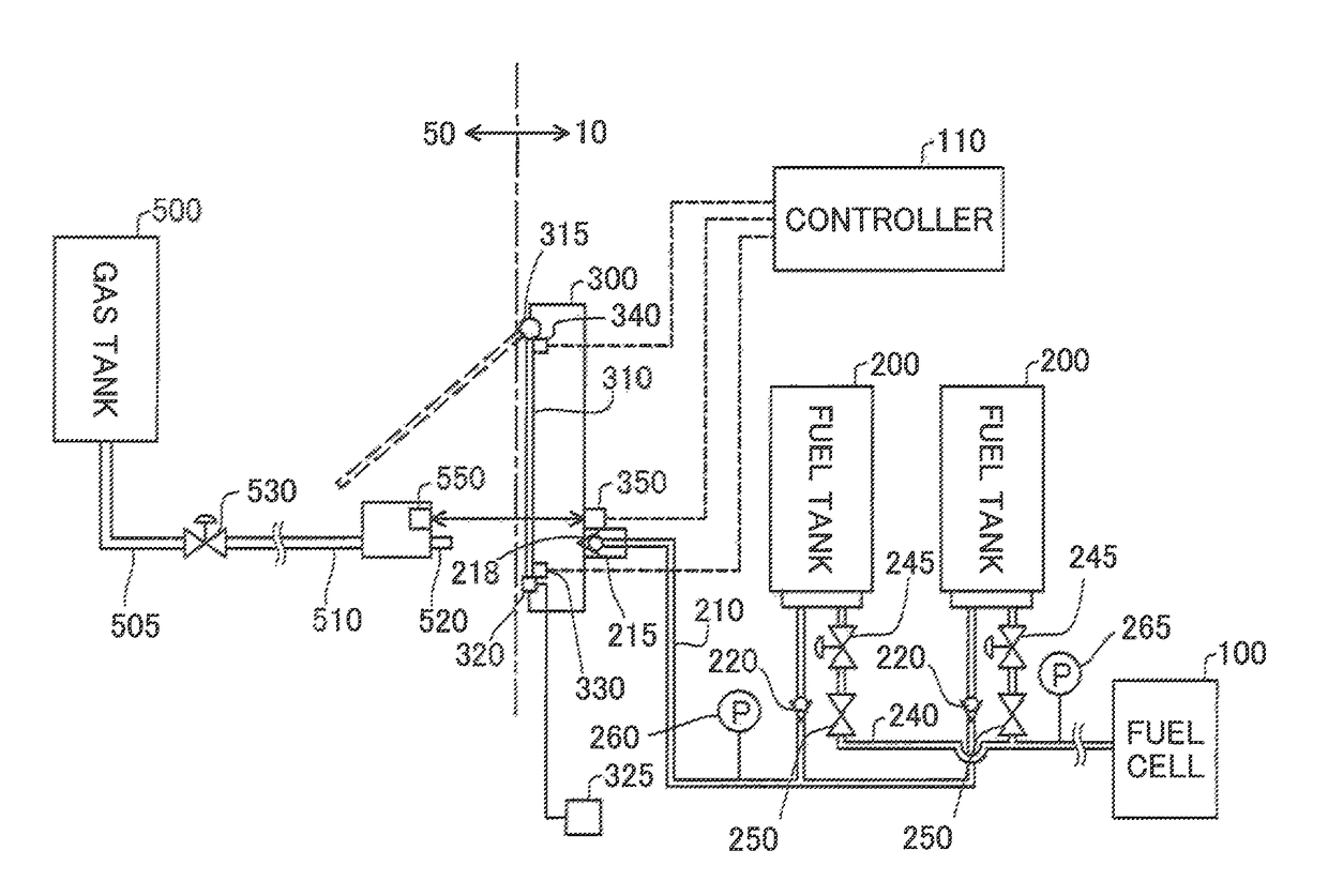
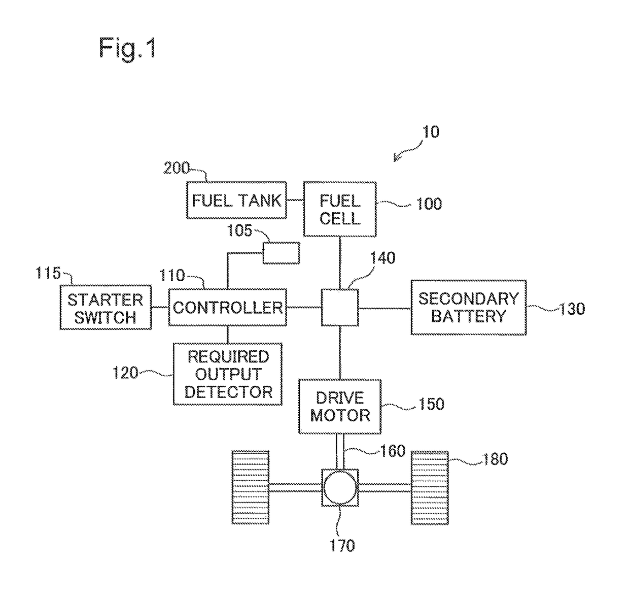
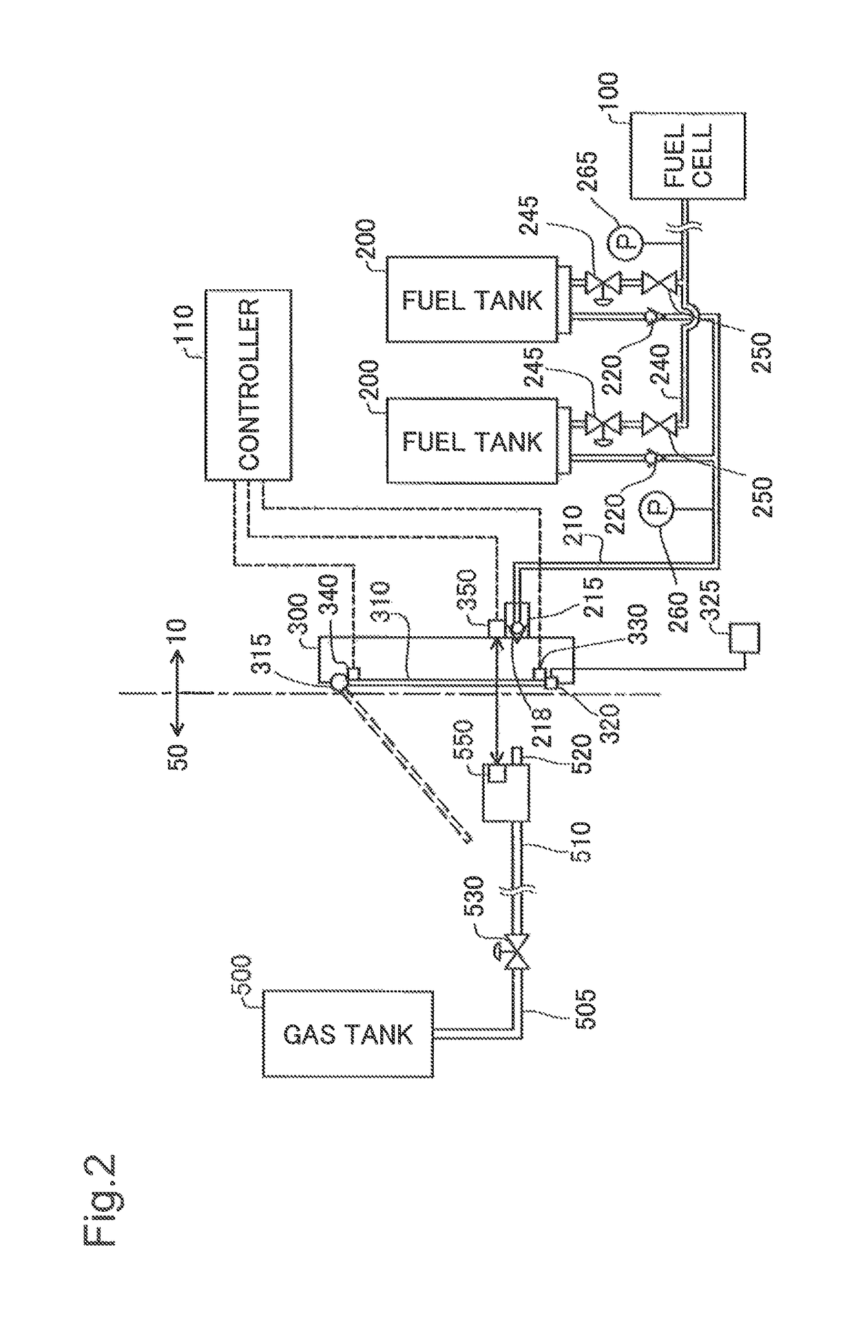
[0023]The following describes some embodiments of the invention with reference to the drawings. FIG. 1 is a diagram schematically illustrating the configuration of a vehicle 10 which a fuel cell is mounted on according to one embodiment of the invention. The vehicle 10 includes a fuel cell 100, a temperature sensor 105 configured to detect temperature of the fuel cell 100, a controller 110 (also called ECU (electronic control unit)), a starter switch 115, a required output detector 120, a secondary battery 130, a power distribution controller 140, a drive motor 150, a driveshaft 160, a power distribution gear 170, wheels 180 and a fuel tank 200.

[0024]The fuel cell 100 is a power generation apparatus that is configured to generate electric power by electrochemical reaction of a fuel gas and an oxidizing gas. The fuel tank 200 is configured to store the fuel gas used for the fuel cell 100. This embodiment uses hydrogen for the fuel gas. The controller 110 controls the operations of th...


PUM

PropertyMeasurementUnit
threshold pressure Pαaaaaaaaaaa
pressureaaaaaaaaaa
speedaaaaaaaaaa

Abstract

There is provided a method of controlling a fuel cell system comprising a fuel cell, a tank that is configured to store a fuel gas filled through a filler port of fuel gas provided in an outer plate of a vehicle, and a main stop valve that is configured to change over between opening and closing to open and close a fuel passage arranged from the tank to the fuel cell. The method comprises controlling the main stop valve to change over from opening to closing in response to detection of an operation for gas filling to fill the fuel gas into the tank, when a control accompanied with opening of the main stop valve is performed during a stop of the vehicle.

Description

CROSS-REFERENCE TO RELATED APPLICATIONS[0001]The present application claims priority from Japanese patent application P2015-89355 filed on Apr. 24, 2015, the content of which is hereby incorporated by reference into this application.BACKGROUND[0002]Field[0003]The present invention relates to a method of controlling a fuel cell system.[0004]Related Art[0005]In a fuel cell system, a fuel gas, for example, hydrogen gas is consumed with operation of a fuel cell for power generation, so that there is a need to fill the hydrogen gas into a tank. A proposed configuration for the fuel cell system transmits data with regard to gas filling to and from a gas supply side by communication in the process of filling the hydrogen gas. For example, a system described in JP 2011-156896A sends temperature data in a tank to the gas supply side by communication. The gas supply side controls the filling rate of hydrogen based on the received data and fills hydrogen at the controlled filling rate.[0006]Th...

Claims


Application Information

Patent Timeline
Patent Type & Authority Patents(United States)
IPC IPC(8): H01M8/043H01M8/04082B60L11/18H01M8/0438H01M8/04089H01M8/04746H01M8/04228H01M8/04955H01M8/04303H01M8/04223H01M8/1018
CPCH01M8/04228B60L11/1883H01M8/0438H01M8/04089H01M8/04201H01M8/04303H01M8/04753H01M8/04955H01M8/04253Y02T90/32H01M2008/1095H01M2250/20H01M8/04298B60L50/72Y02T90/40Y02E60/50B60L58/31B60L58/30H01M8/04388B60Y2400/202B60L53/54
Inventor NADA, MITSUHIROTANO, YUTAKA
Owner TOYOTA JIDOSHA KK
Why Eureka
Try Eureka