X-ray analyzing apparatus and method

a technology of x-ray analyzing and apparatus, applied in the direction of material analysis using radiation diffraction, instruments, handling using diffraction/reflection/reflection, etc., can solve the problems that the fluorescence analysis method is incapable of avoiding the diffracted x-rays generated from the sample of a kind having its crystalline structure, and the analysis cannot be accomplished depending on the sample, so as to facilitate an accurate

Active Publication Date: 2015-09-29
RIGAKU CORP
View PDF7 Cites 2 Cited by
  • Summary
  • Abstract
  • Description
  • Claims
  • Application Information

AI Technical Summary

Benefits of technology

[0013]In view of the foregoing, the present invention has been devised to eliminate the problems and inconveniences inherent in the prior art discussed above and is intended to provide an X-ray analyzing apparatus and method, which are effective to suppress and avoid the scattered X-rays and impurity X-rays (impurity lines) both generated from the neighborhood of an edge of a disc-shaped sample of a kind, having a crystalline structure, and apparatus structural components in the vicinity of the sample and also to circumvent the diffracted X-rays generated from the sample, to thereby facilitate an accurate analysis easily.
[0017]Well, in order to suppress and avoid the scattered X-rays and the impurity X-rays generated from the neighborhood of the edge of the disc-shaped sample and the apparatus structural components in the vicinity of the sample, it is ideal to perform the measurement under a condition in which when viewed in a plane the direction of travel of the primary X-rays and the direction from the center of the sample to the point of measurement coincide with each other, that is, under a condition in which the angle of rotation of the sample from the initial condition coincides with the θ coordinate of the point of measurement in the R−θ coordinates of the sample. However, if the angle of rotation from that condition is within a range of ±θ1 determined by the previously discussed equation (1), the scattered X-rays and the impurity X-rays can be sufficiently suppressed and avoided.
[0019]In view of the above, in the X-ray analyzing apparatus designed in accordance with the first aspect of the present invention, the control unit stores a predetermined angle which is equal to or smaller than an angle 2θ1, but not smaller than 4° and by automatically acquiring a diffraction pattern and scanning it by a linear line representative of the intensity of the secondary X-rays in a direction of highness and lowness of the intensity, the candidate points, at which the diffracted X-rays can be avoided and adjoining each other at the predetermined angle or smaller at the angle of rotation on the diffraction pattern, followed by storage of the respective angles of rotation at that candidate points. And, depending on the coordinates of the point of measurement of the sample, one of the stored angles of rotation, which is most proximate to (or matching with) the coordinates of the point of measurement is read out, and the sample is set to the read out angle of rotation with the point of measurement of the sample arranged within the field of view of the detector.
[0020]As hereinabove described, according to the X-ray analyzing apparatus of the structure according to the first aspect of the present invention, since with respect to the arbitrary point of measurement lying in the vicinity of the edge of the sample, the sample can be set to the angle of rotation effective to avoid the diffracted X-rays within a range of the predetermined angle which center is the ideal condition for suppressing and avoiding the scattered X-rays and the impurity X-rays, not only can the scattered X-rays and the impurity X-rays generated from the neighborhood of the edge of the disc-shaped sample of a kind having the crystalline structure and the apparatus structural components in the vicinity of the sample be suppressed and avoided, but also the diffracted X-rays generated from the sample can be avoided, thus making it possible to achieve an accurate analysis easily.
[0023]According to the X-ray analyzing apparatus according to the second aspect of the present invention, since with the fluorescent X-rays from the principal component of the sample taken as an internal standard line the intensity of the secondary X-rays of the wavelength of the monochromated primary X-rays is corrected, it is possible to eliminate any change in angle of incident of the primary X-rays upon the sample as a result of fluctuation of a shaft of the rotating unit to enable a further accurate diffraction pattern to be acquired and, accordingly, a further accurate analysis can be accomplished.

Problems solved by technology

Although the fluorescence analyzing method disclosed in the patent document 1 referred to above appears to be effective in avoiding the incidence of the diffracted X-rays generated from the sample of a kind having a crystalline structure of a rotational symmetry, such fluorescence analyzing method is incapable of avoiding the diffracted X-rays generated from the sample of a kind having its crystalline structure that is not of a rotational symmetry.
On the other hand, the total reflection X-ray fluorescence spectrometer disclosed in the patent document 2 referred to above appear to be effective in suppressing influences brought about by the scattered X-rays generated from the neighborhood of the sample, such total reflection X-ray fluorescence spectrometer has been found problematic in that since no attention is drawn to avoid the diffracted X-rays generated from the sample, no diffracted X-ray cannot be avoided even though the sample is set to a position effective to eliminate the influences brought about by the scattered X-rays, and, therefore, an accurate analysis cannot be accomplished depending on the sample.

Method used


Image

  • X-ray analyzing apparatus and method
  • X-ray analyzing apparatus and method
  • X-ray analyzing apparatus and method

Examples


Embodiment Construction

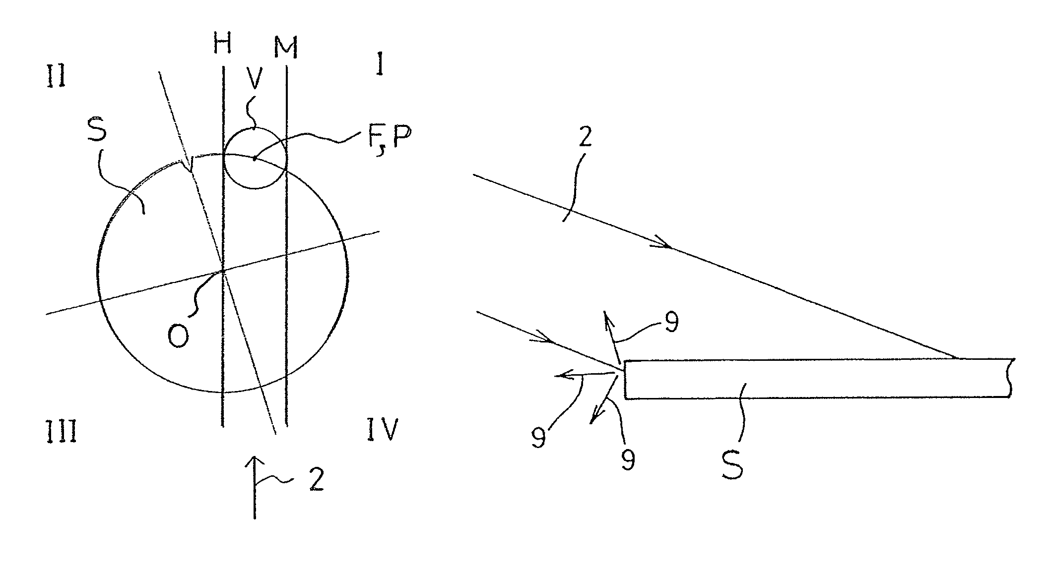
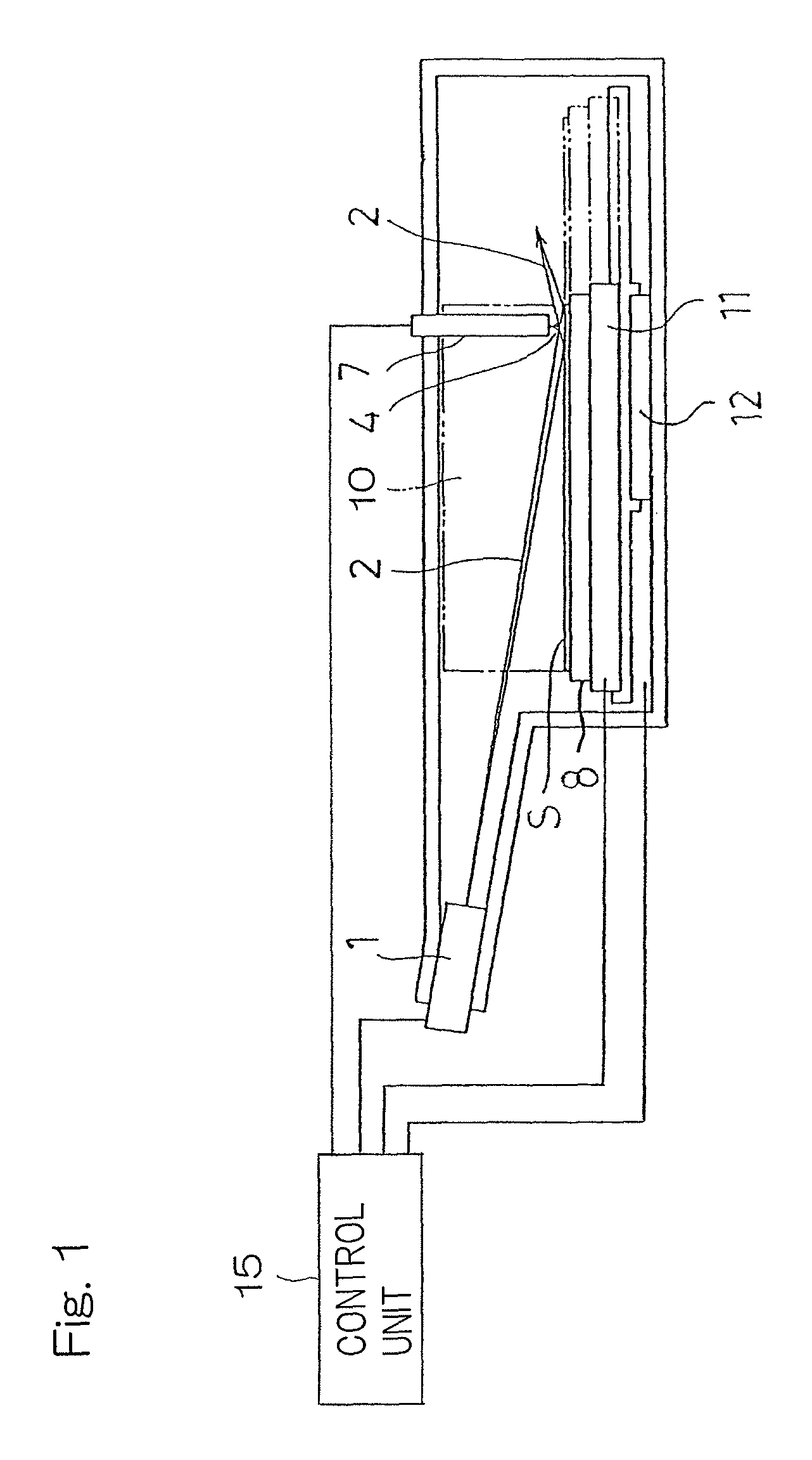
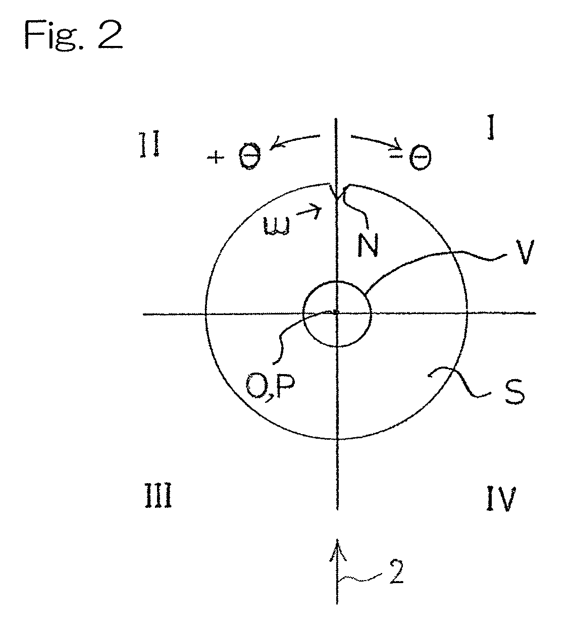
[0043]Hereinafter, an X-ray analyzing apparatus designed in accordance with a preferred embodiment of the present invention will be described in detail. The X-ray analyzing apparatus is a total reflection X-ray fluorescence spectrometer which includes, as best shown in FIG. 1, a sample table 8 on which a disc-shaped sample S, such as, for example, a silicon wafer, of a kind having a crystalline structure is placed, an X-ray source 1 (including, for example, an X-ray tube and a spectroscopic device) to radiate primary X-rays 2, which have been monochromated, towards the sample S, a detector 7 to detect secondary X-rays 4, containing fluorescent X-rays, diffracted X-rays and others, which are generated from the sample S, and which is in the form of a semiconductor detector such as, for example, SDD, a parallel shifting unit 12 for translating the sample table 5 so that an arbitrary point of measurement on a measuring surface of the sample S may be disposed within the field of view V o...


PUM

PropertyMeasurementUnit
radiusaaaaaaaaaa
radiusaaaaaaaaaa
angleaaaaaaaaaa

Abstract

An X-ray analyzing apparatus is such that a diffraction pattern, in which the intensity of secondary X-rays (4) is associated with the angle of rotation of a sample (S), is stored; while the pattern is scanned by a line of the secondary X-rays (4) intensity in a direction of highness and lowness, points on the pattern having not higher intensity than the line are taken as candidate points; respective angles of rotation of the candidate points, when the maximum value of the difference in angle of rotation between the neighboring candidate points attains a predetermined angle, are stored; depending on coordinates of a point of measurement, the angle of rotation proximate to the coordinates is read out from the stored angles; and the sample (S) is set to the read out angle and the point of measurement is arranged within the field of view (V) of a detector (7).

Description

CROSS REFERENCE TO THE RELATED APPLICATION[0001]This application is based on and claims Convention priority to Japanese patent application No. 2011-248202, filed Nov. 14, 2011, the entire disclosure of which is herein incorporated by reference as a part of this application.BACKGROUND OF THE INVENTION[0002]1. Field of the Invention[0003]The present invention relates to an X-ray analyzing apparatus and a method therefor for measuring an arbitrary point of measurement of a disc shaped sample such as, for example, a wafer.[0004]2. Description of Related Art[0005]Hitherto, the analysis of, for example, a wafer has been carried out by irradiating a sample surface with primary X-rays, detecting secondary X-rays emanating from the sample surface and then measuring the intensity of the secondary X-rays emitted by the sample surface. In the practice of this conventional X-ray analysis, it has been well recognized that a sample of a kind having a crystalline structure, such as, for example, a ...

Claims


Application Information

Patent Timeline
Patent Type & Authority Patents(United States)
IPC IPC(8): G01N23/20G21K1/06G01N23/223G01N23/22
CPCG01N23/223G01N23/20008G01N23/20016G01N23/2204G21K1/06G01N23/20G01N2223/076
Inventor FUKUDA, TOMOYUKISHIMIZU, KOSUKEIKESHITA, AKIHIRO
Owner RIGAKU CORP
Why Eureka
Try Eureka