Method of generating multi-band RF pulses

a multi-band, pulse-generating technology, applied in the field of magnetic resonance imaging, to achieve the effect of reducing or eliminating artifacts, reducing non-desired side lobes or additional signals, and reducing or eliminating differences in the main lobes

Active Publication Date: 2020-02-04
KONINKLJIJKE PHILIPS NV
View PDF8 Cites 0 Cited by
  • Summary
  • Abstract
  • Description
  • Claims
  • Application Information

AI Technical Summary

Benefits of technology

[0011]These features may have the advantage of providing a preventive method for avoiding or suppressing unintentionally excited slices. In other terms, the present method may provide an a priori correction of the side-bands that result from the unintentionally excitation of slices. This may increase the quality of the acquired MR data and may save processing resources that would otherwise be required for a posteriori correction of sidebands in reconstructed images.
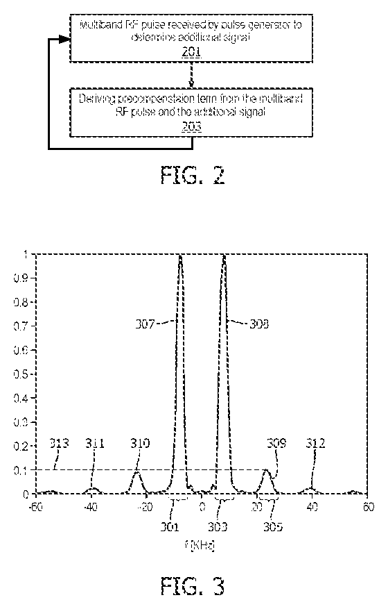
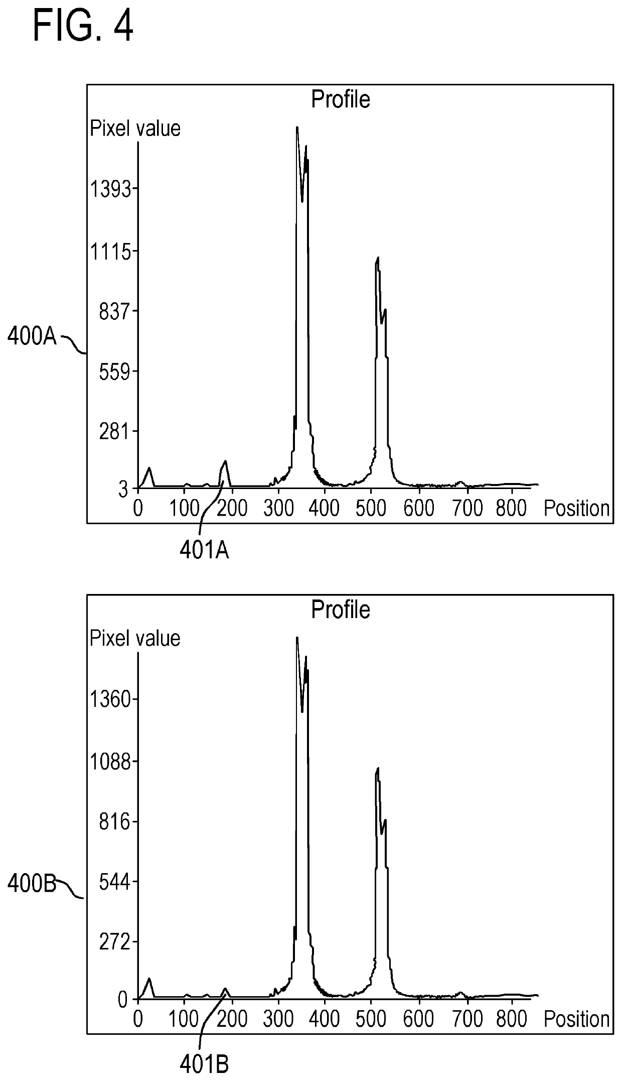
[0012]According to one embodiment, determining the additional signal comprises exciting the two slices using the first multiband RF pulse; reconstructing an image using acquired MR data for the two slices in response to the first multiband RF pulse; and identifying using the reconstructed image the additional signal. The features of this embodiment may be performed during a calibration scan of the MRI system. The calibration scan is typically carried out prior to a diagnostic scan of the subject. This embodiment may have the advantage of providing an accurate method for identifying the additional signals (also referred to herein as side-band signals or side lobes or side lobe signals).
[0015]According to one embodiment, determining the additional signal comprises providing history data indicative of one or more multiband RF pulses and associated frequency spectrums; identifying a multiband RF pulse of the one or more multiband RF pulses that corresponds to the first multiband RF pulse; and identifying the additional signal using the frequency spectrum associated with the identified multiband RF pulse. For example, the second multiband RF pulse may be selected as a multiband RF pulse of the one or more multiband RF pulses whose associated frequency spectrum corresponds to the expected frequency spectrum of the first multiband RF pulse having no additional signals. This embodiment may have the advantage of providing an automatic method for identifying the additional (side-band) signal.
[0016]According to one embodiment, identifying comprises: determining the geometry or the size of the subject; using the determined geometry or size for determining a circumference area around the first and second frequency bands in the frequency spectrum; identifying the additional signal within the circumference area. The geometry or the size of the subject that is determined comprises the geometry of the size of the portion of the subject that is imaged e.g. that is inside an imaging zone of the MRI system. This may provide an efficient method for suppressing only side-band signals that may affect the desired image. For example, a side-band signal that may not induce an artifact effect in an image area that covers the portion of the subject that has been imaged may not be treated or identified.
[0020]According to one embodiment, the method further comprises: repeating the determining of the additional signal and the deriving step c) using the second multiband RF pulse as the first multiband RF pulse in step b) until the suppressed at least part of the additional signal is higher than a predetermined minimum side-band signal amplitude. This may have the advantage of further reducing nondesired side lobe or additional signals, for multiple main lobe signals.
[0021]According to one embodiment, the method further comprises exciting the two slices using the second multiband RF pulse for reconstructing signals from RF coils of the MRI system, wherein reconstructing a signal from an RF coil of the RF coils is performed in accordance with formula Sq*(f*x)q,1 where: q refers to a slice of the two slices and the additional slice, Sq is a sensitivity of the RF coil for q, f is the normalized amplitude of the signal at q and x is the signal from q. As there may be still remaining side lobes after performing the first suppression method described by the previous embodiments, the present method may have the advantage of reducing or eliminating the artifacts from images of the main lobes that may be caused by the remaining side lobes. Further, since the main lobe signals are not equal and the difference is reflected in “f” in the reconstruction formula, the differences in the main lobes may also be corrected. For example, the MRI system may comprise at least one RF coil per slice of the two slices and the additional slice. This embodiment may be performed during a physical scan.

Problems solved by technology

However, due to the RF hardware limitation, multi-band excitations show side-band artefacts in resulting images especially when high frequency modulation multi-band excitations and / or high power scans are used.

Method used


Image

  • Method of generating multi-band RF pulses
  • Method of generating multi-band RF pulses
  • Method of generating multi-band RF pulses

Examples


Embodiment Construction

[0043]In the following, like numbered elements in the figures are either similar elements or perform an equivalent function. Elements which have been discussed previously will not necessarily be discussed in later figures if the function is equivalent.

[0044]Various structures, systems and devices are schematically depicted in the figures for purposes of explanation only and so as to not obscure the present invention with details that are well known to those skilled in the art. Nevertheless, the attached figures are included to describe and explain illustrative examples of the disclosed subject matter.

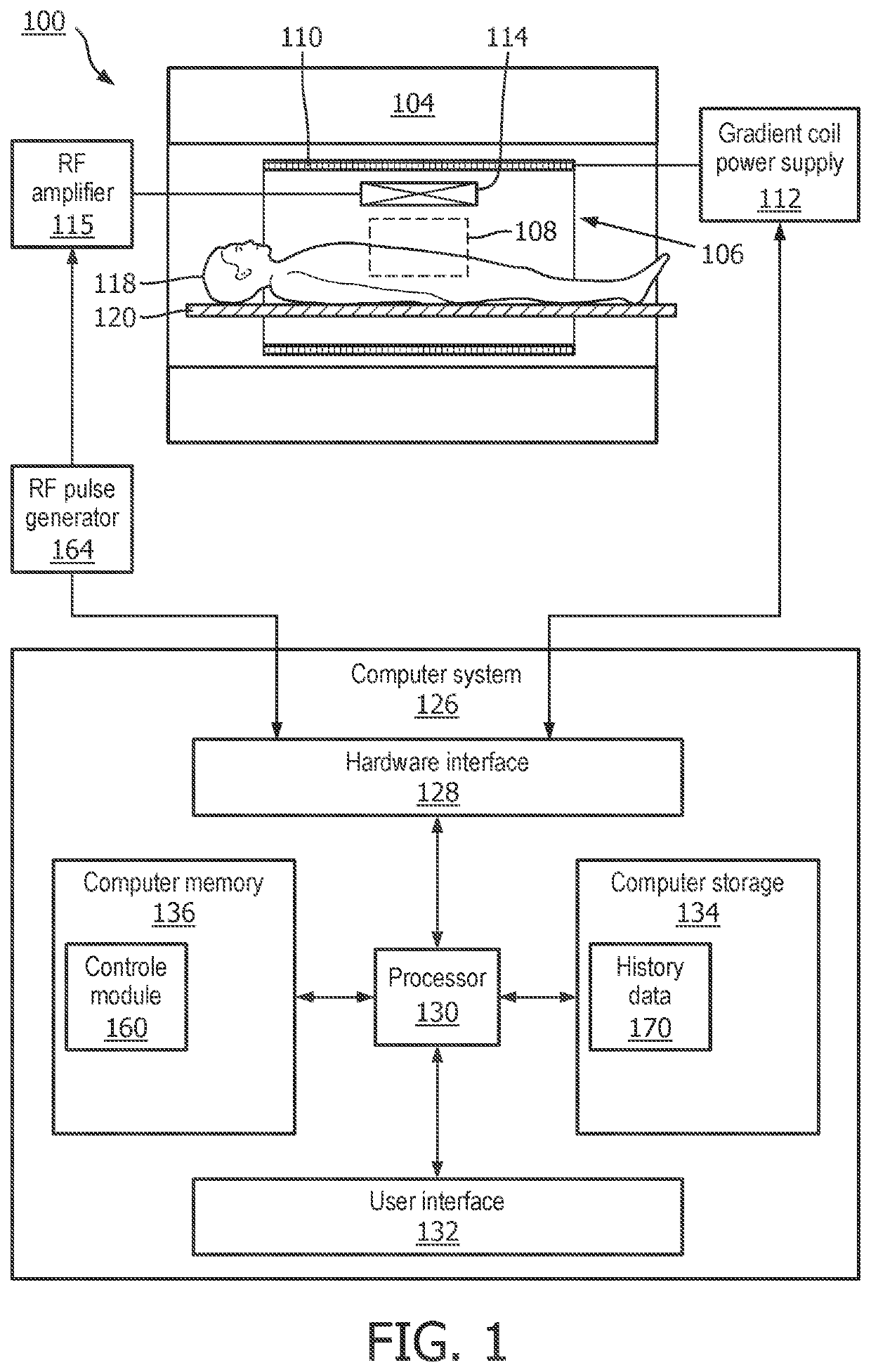
[0045]FIG. 1 illustrates an example of a magnetic resonance imaging system 100. The magnetic resonance imaging system 100 comprises a magnet 104. The magnet 104 is a superconducting cylindrical type magnet 100 with a bore 106 through it. The use of different types of magnets is also possible for instance it is also possible to use both a split cylindrical magnet and a so called open mag...


PUM


Abstract

The present invention relates to a method for side-band suppression in a Magnetic Resonance imaging, MRI, system (100), the method comprising providing a first multiband RF pulse for simultaneously exciting at least two slices in a subject (118) at a first and a second frequency band (301,303) and to acquire using the MRI system (100) signals (307, 308) from the excited two slices and at least one additional signal (309) at a third frequency band (305), the additional signal (309) resulting from a sideband excitation of a slice different from the two slices; using the first multiband RF pulse for determining the additional signal (309); deriving a pre-compensating term from the first multiband RF pulse and the additional signal (309), adding the pre-compensating term to the first multiband RF pulse to obtain a second multiband RF pulse, thereby replacing the first multiband RF pulse by the second multiband RF pulse for suppressing at least part of the additional signal (309).

Description

CROSS REFERENCE TO RELATED APPLICATIONS[0001]This application is a U.S. national phase application of International Application No. PCT / EP2015 / 068812, filed on Aug. 17, 2015, which claims the benefit of EP 14185295.4 filed Sep. 18, 2014, EP 15152589.6 filed Jan. 27, 2015, and PCT / CN2015 / 0761689 filed Apr. 9, 2015, which are incorporated herein by reference.TECHNICAL FIELD OF THE INVENTION[0002]The invention relates to magnetic resonance imaging, in particular to a method of generating multi-band RF pulses.BACKGROUND OF THE INVENTION[0003]Multi-band excitation accelerates multi slice magnetic resonance imaging (MRI) scans by exciting and acquiring more than one slice e.g. at the same time. However, due to the RF hardware limitation, multi-band excitations show side-band artefacts in resulting images especially when high frequency modulation multi-band excitations and / or high power scans are used. For example, the side-band artefacts may be the result of spectra or side-band signals t...

Claims


Application Information

Patent Timeline
Patent Type & Authority Patents(United States)
IPC IPC(8): G01R33/48G01R33/565G01R33/561G01R33/54G01R33/483
CPCG01R33/561G01R33/483G01R33/54G01R33/4816G01R33/565G01R33/4835G01R33/543G01R33/5659
Inventor XIE, BINNISTI GRIGOLETTO BORGONOVI, ARTHUR FELIPECHEN, ZHAOLINFUDERER, MIHA
Owner KONINKLJIJKE PHILIPS NV
Why Eureka
Try Eureka