Method for monitoring blind spot of monitoring vehicle and blind spot monitor using the same

a technology for monitoring vehicles and monitors, applied in vehicle sub-unit features, instruments, image enhancement, etc., can solve problems such as putting further strain on drivers, unable to see through, and algorithms may show limited detection rate constraints

Active Publication Date: 2018-04-03
STRADVISION
View PDF4 Cites 45 Cited by
  • Summary
  • Abstract
  • Description
  • Claims
  • Application Information

AI Technical Summary

Benefits of technology

[0017]It is still yet another object of the present invention to detect the monitored vehicle located in the blind spot accurately using a CNN.

Problems solved by technology

This has been a problem because there can be an accident with the monitored vehicle in the blind spot if the driver changes lanes without seeing the monitored vehicle.
However, even when the convex mirror is added onto the side view mirror, the driver must see the blind spot with his / her own eyes to change lanes which puts further strain to the driver, and there may exist the blind spot that still cannot be seen through the convex mirror even if the driver alters his / her head position.
However, those algorithms may show limited detection rates constrained by external environment, shape of the objects, and a configuration of a system.
Because an accurate detection requires a number of visual processing, a computational load is very heavy.
Therefore, real-time detection may be difficult in an embedded system due to limited processing resources.
A fully connected (FC) determines whether the candidate is a vehicle, however, many of the candidates overlap each other and the RPN consumes much running time performing computation on these redundant candidates which hardly help improve a detection rate.
However, an algorithm for recognition of the monitored vehicle using the optical flow method has much dependence on a change of a state of a background and a visual noise, and requires an enormous computational load, therefore, real-time detection of the monitored vehicle is not easy.

Method used


Image

  • Method for monitoring blind spot of monitoring vehicle and blind spot monitor using the same
  • Method for monitoring blind spot of monitoring vehicle and blind spot monitor using the same
  • Method for monitoring blind spot of monitoring vehicle and blind spot monitor using the same

Examples


Embodiment Construction

[0028]Detailed explanation on the present invention to be made below refer to attached drawings and diagrams illustrated as specific embodiment examples under which the present invention may be implemented to make clear of purposes, technical solutions, and advantages of the present invention. These embodiments are described in sufficient detail to enable those skilled in the art to practice the invention.

[0029]Besides, in the detailed description and claims of the present invention, a term “include” and its variations are not intended to exclude other technical features, additions, components or steps. Other objects, benefits and features of the present invention will be revealed to one skilled in the art, partially from the specification and partially from the implementation of the present invention. The following examples and drawings will be provided as examples but they are not intended to limit the present invention.

[0030]Moreover, the present invention covers all possible com...


PUM


Abstract

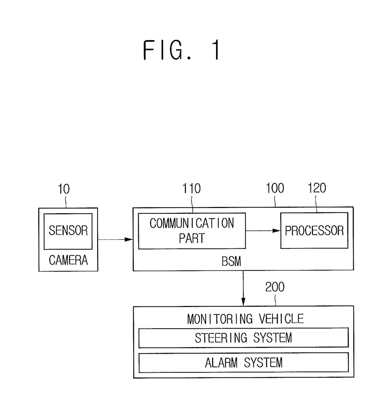
A method of monitoring a blind spot of a monitoring vehicle by using a blind spot monitor. The method includes steps of: the blind spot monitor (a) acquiring a feature map from rear video images, on condition that video images with reference vehicles in the blind spot are acquired, reference boxes for the reference vehicles are created, and the reference boxes are set as proposal boxes; (b) acquiring feature vectors for the proposal boxes on the feature map by pooling, inputting the feature vectors into a fully connected layer, acquiring classification and regression information; and (c) selecting proposal boxes by referring to the classification information, acquiring bounding boxes for the proposal boxes by using the regression information, confirming whether the bounding boxes match their corresponding proposal boxes, and determining whether the monitored vehicle is in the proposal boxes to determine the monitored vehicle is in the blind spot.

Description

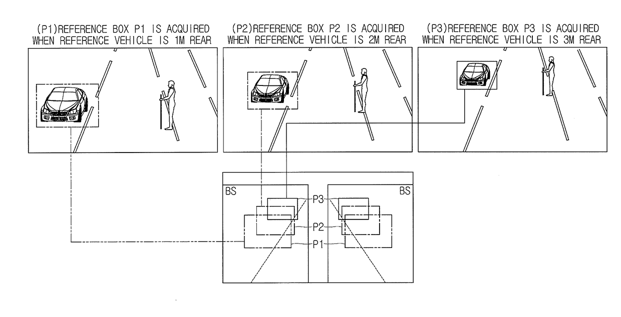
FIELD OF THE INVENTION[0001]The present invention relates to a method for monitoring a blind spot of a monitoring vehicle and a blind spot monitor using the same; and more particularly, to the method of monitoring a blind spot of a monitoring vehicle, including steps of: (a) the blind spot monitor, if rear video images for testing are acquired from the monitoring vehicle in operation, acquiring at least one feature map for testing from the rear video images for testing, on condition that the blind spot monitor completes processes of (i) acquiring rear video images for sampling with regard to one or more reference vehicles located per distance from the monitoring vehicle and located in the blind spot of the monitoring vehicle, (ii) creating reference boxes corresponding to the reference vehicles in each of the rear video images for sampling, and (iii) setting the reference boxes as m proposal boxes which serve as candidate regions in the blind spot of the monitoring vehicle, wherein ...

Claims


Application Information

Patent Timeline
Patent Type & Authority Patents(United States)
IPC IPC(8): G06K9/00G06N3/08G06K9/62G06K9/48G06K9/78G06K9/20G06N3/04B60R1/00G06V10/22G06V10/25G06V10/764G06V10/82
CPCG06K9/00791G06K9/2054G06K9/78G06K9/481G06K9/6267G06N3/08G06N3/04G06K9/6256G06K2209/21B60Y2400/3015B60R1/00B60R2300/802B60R2300/30G06V20/56G06V10/22G06V10/454G06V10/25G06V2201/07G06V10/82G06V10/764G06N3/045G06F18/2413G06T7/223G06T7/11G06T5/20B60R1/025B60W40/02B60W30/18163G06T2210/12G06T2207/20081G06F18/24G06F18/214
Inventor KIM, YONGJOONGNAM, WOONHYUNBOO, SUKHOONSUNG, MYUNGCHULYEO, DONGHUNRYU, WOOJUJANG, TAEWOONGJEONG, KYUNGJOONGJE, HONGMOCHO, HOJIN
Owner STRADVISION
Why Eureka
Try Eureka