
Automated patient-specific method for biomechanical analysis of bone

a patient-specific method and bone technology, applied in image data processing, health-index calculation, medical simulation, etc., can solve the problems of bone or remaining bone being too weak to withstand these stresses, requiring too much fea expertise, and too time-consuming

Active Publication Date: 2018-04-10
PERSIMIO LTD
View PDF10 Cites 3 Cited by
  • Summary
  • Abstract
  • Description
  • Claims
  • Application Information

AI Technical Summary

Benefits of technology

The system provides accurate and efficient prediction of bone fracture risk and optimal implant placement, reducing the need for manual intervention and improving clinical efficiency by generating patient-specific models and ensuring numerical accuracy.

Problems solved by technology

However, if the bone is weak (e.g. from osteoporosis) or damaged (e.g. from tumors invading the bone wall or preexisting fractures), or if a portion of the bone is to be replaced by an implant, the bone or remaining bone may be too weak to withstand these stresses.
In the case of replacing a portion of the bone by an implant, implants sometimes fail or loosen and sometimes this leads to fracture of the bone to which they are attached.
It is claimed in U.S. Pat. No. 8,126,234 that to mesh ab initio for each individual patient from captured geometry requires too much FEA expertise and is too time consuming.
Therefore, these problems make it infeasible to use the method of U.S. Pat. No. 8,126,234 in a clinical setting.
According to U.S. Pat. No. 8,126,234, fully automatic meshing ab initio results in meshed models containing a large enough number of low-order finite elements that solving such meshes becomes infeasible on the timescales required in a clinical context.
Care must be taken in converting grey scale data to material properties, as inaccurate material properties can invalidate the results.
Furthermore, U.S. Pat. No. 8,126,234 does not address the numerical accuracy of the results, nor the validation of these by past experiments, or describe any means by which errors can be assessed or controlled.

Method used


Image

  • Automated patient-specific method for biomechanical analysis of bone
  • Automated patient-specific method for biomechanical analysis of bone
  • Automated patient-specific method for biomechanical analysis of bone

Examples


example 1

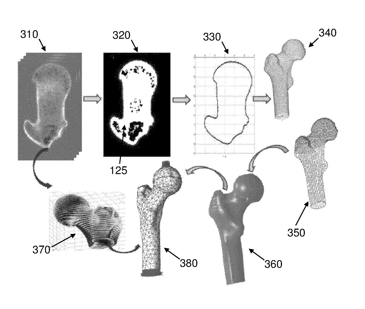
[0298]The methods were examined on different fresh frozen bones with different CT resolutions. To compare between both methods and to assure model's accuracy, several measurements were taken and compared to the geometrical model. The comparison of the outer contour dimensions generated from CT data and the real femur shows a maximum error of 2% (usually less than 1 mm which is in the range of the CT resolution and the measurements tool error).

example 2

[0299]Validation of the material properties was performed by applying a load of 1000 N to a section of a thawed fresh-frozen human femur. The femur was scanned by quantitative computed tomography (QCT) and thereafter loaded (in vitro experiments) by the quasi-static load. QCT scans were manipulated to generate a high-order FE bone model with distinct cortical and trabecular regions having inhomogeneous isotropic elastic properties with Young's modulus represented by continuous spatial functions. Sensitivity analyses were performed to quantify parameters that have the most influence on the mechanical response. FE results were compared to displacements and strains measured in the experiments.

[0300]After defrosting, soft tissue was removed from the bone and the bone was degreased with ethanol. The proximal femur was cut and fixed concentrically into a cylindrical sleeve by six bolts and a PMMA substrate and was scanned in two different environments. QCT scans were performed using a Phi...


PUM


Abstract

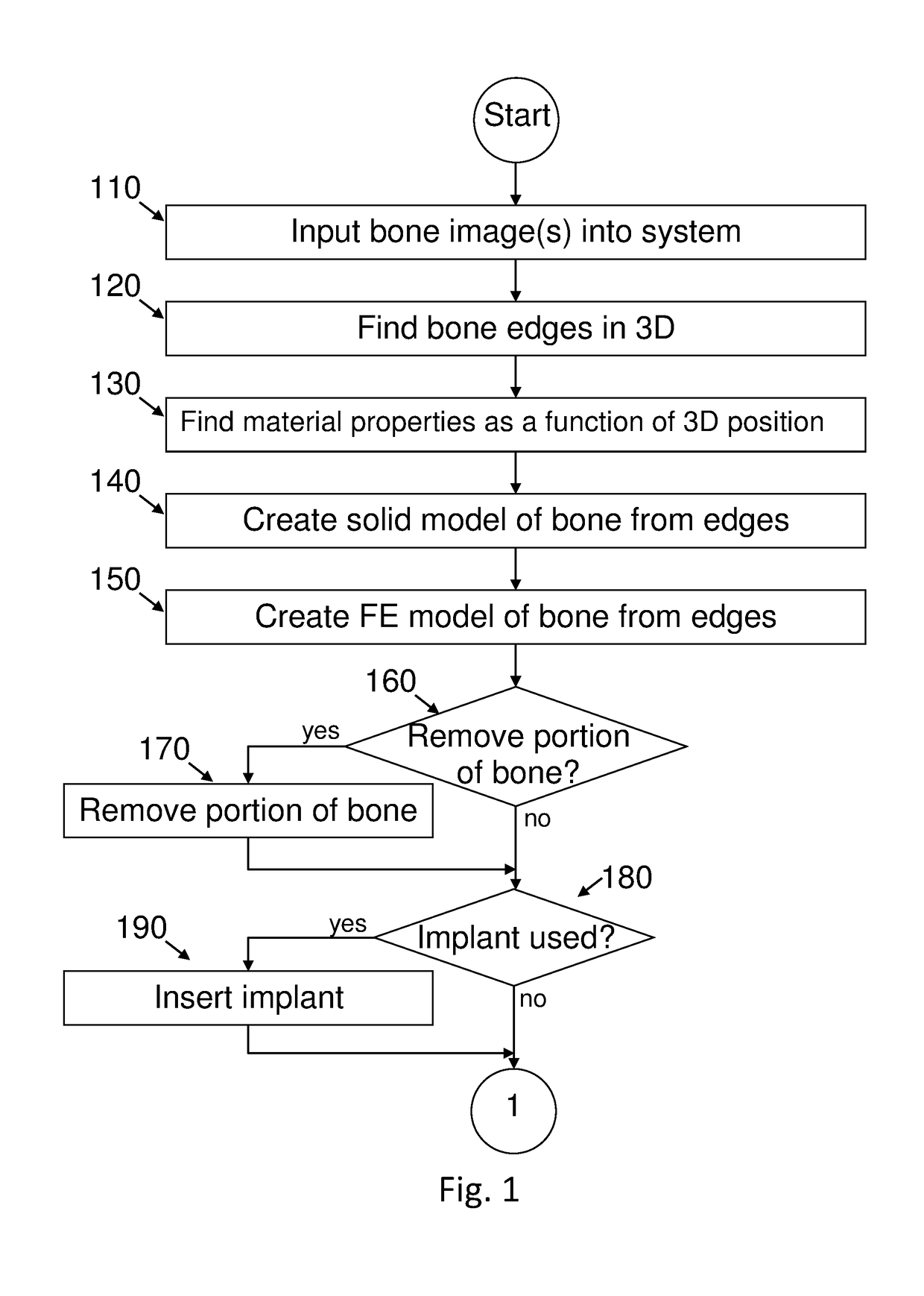
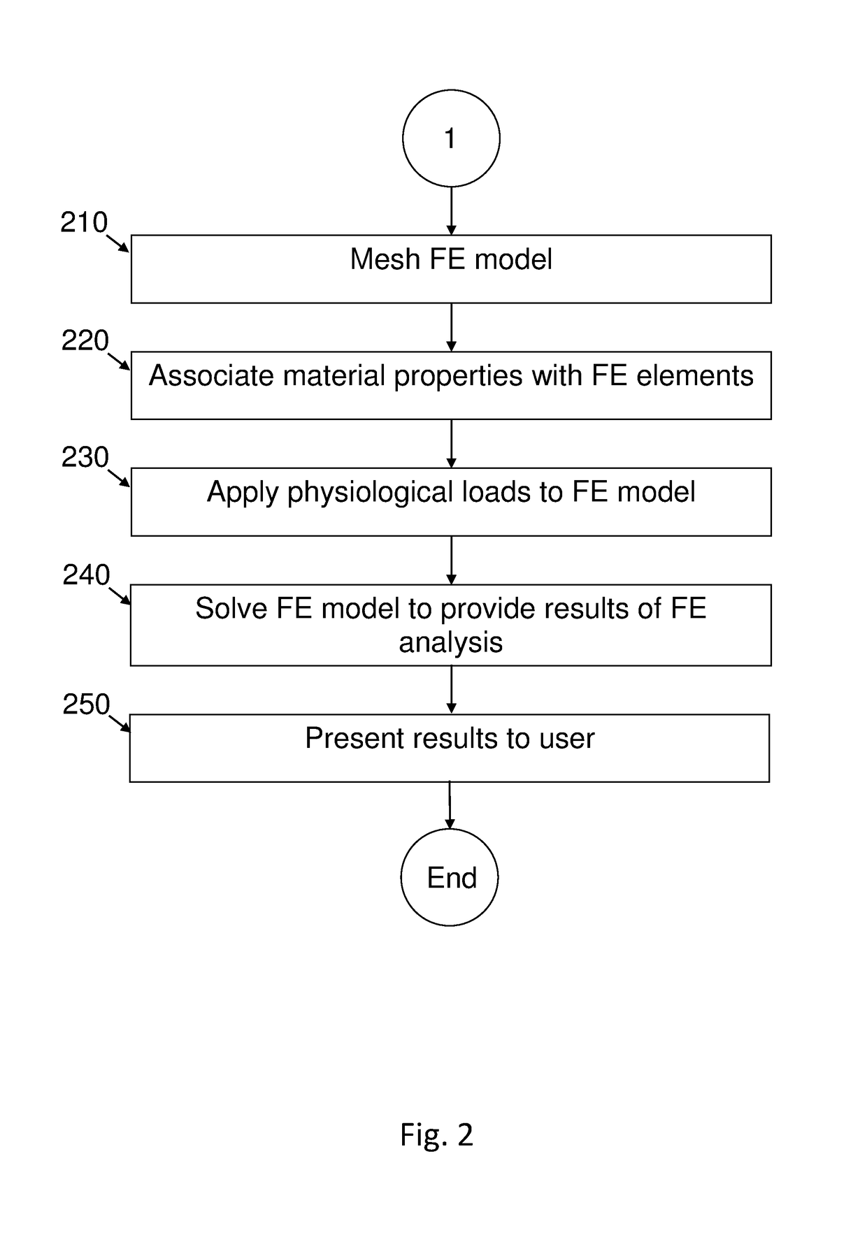
A computer-implemented method for providing FEA analysis of at least a portion of at least one bone in a patient, the method comprising steps of: providing at least one image of at least a portion of a bone; selecting at least a portion of the bone; automatically performing an FE analysis of the selected portion of the bone; and displaying at least one result of the FE analysis. Bone selection and display of the bone, the selected portion thereof, and the results of the FE analysis occur via a hand-held device, with processing and data storage performed remotely.

Description

FIELD OF THE INVENTION[0001]The present invention generally pertains to a system and method for using finite element analysis of models of a patient's bone under physiological loading to indicate likely outcome for the patient.BACKGROUND OF THE INVENTION[0002]Bone endures large stresses from habitual and sporadic loading. Under normal circumstances, bone will withstand these stresses without damage. However, if the bone is weak (e.g. from osteoporosis) or damaged (e.g. from tumors invading the bone wall or preexisting fractures), or if a portion of the bone is to be replaced by an implant, the bone or remaining bone may be too weak to withstand these stresses. Therefore, a biomechanical analysis of the bone (or bone-implant system) can be a valuable aid in deciding the best future course of treatment for the patient. For example, if the bone is likely to fracture under the stresses of normal living, more aggressive treatment of osteoporosis would be indicated. For another example, a...

Claims


Application Information

Patent Timeline
Patent Type & Authority Patents(United States)
IPC IPC(8): G06K9/00A61B6/00G06T17/20A61B34/10A61B5/00G06T19/20A61B5/055A61B6/03G06F17/50
CPCA61B34/10A61B5/055A61B5/4504A61B5/4884A61B5/7275A61B6/032A61B6/505A61B6/5217A61B6/5258G06F17/5009G06T17/20G06T19/20A61B5/0037G06T2200/04A61B2034/102G16H30/40G16H40/67G16H50/30G16H50/50G06F30/20
Inventor YOSIBASH, ZOHARTRABELSI, NIRMYERS, KENTMILGROM, CHARLES
Owner PERSIMIO LTD
Learn More