Electrical generation arrangement for an aircraft

a technology of electric generation and aircraft, applied in the direction of machines/engines, efficient propulsion technologies, mechanical devices, etc., can solve the problems of large frequency range, heavy electrical machines, and large size, and achieve the effect of more lightweight and efficien

Active Publication Date: 2018-04-10
ROLLS ROYCE PLC
View PDF10 Cites 6 Cited by
  • Summary
  • Abstract
  • Description
  • Claims
  • Application Information

AI Technical Summary

Benefits of technology

[0006]Providing a disconnection device in this way allows for a more lightweight and efficient means of selectively taking power from the low pressure spool.

Problems solved by technology

The reduced speed range is preferable because the electrical frequency outputted by the generators is proportional to spool speed and a large frequency range can be problematic.
Also, having a larger speed range generally results in larger, heavier electrical machines.

Method used


Image

  • Electrical generation arrangement for an aircraft
  • Electrical generation arrangement for an aircraft
  • Electrical generation arrangement for an aircraft

Examples


Embodiment Construction

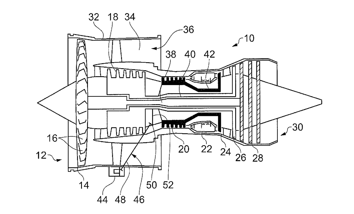
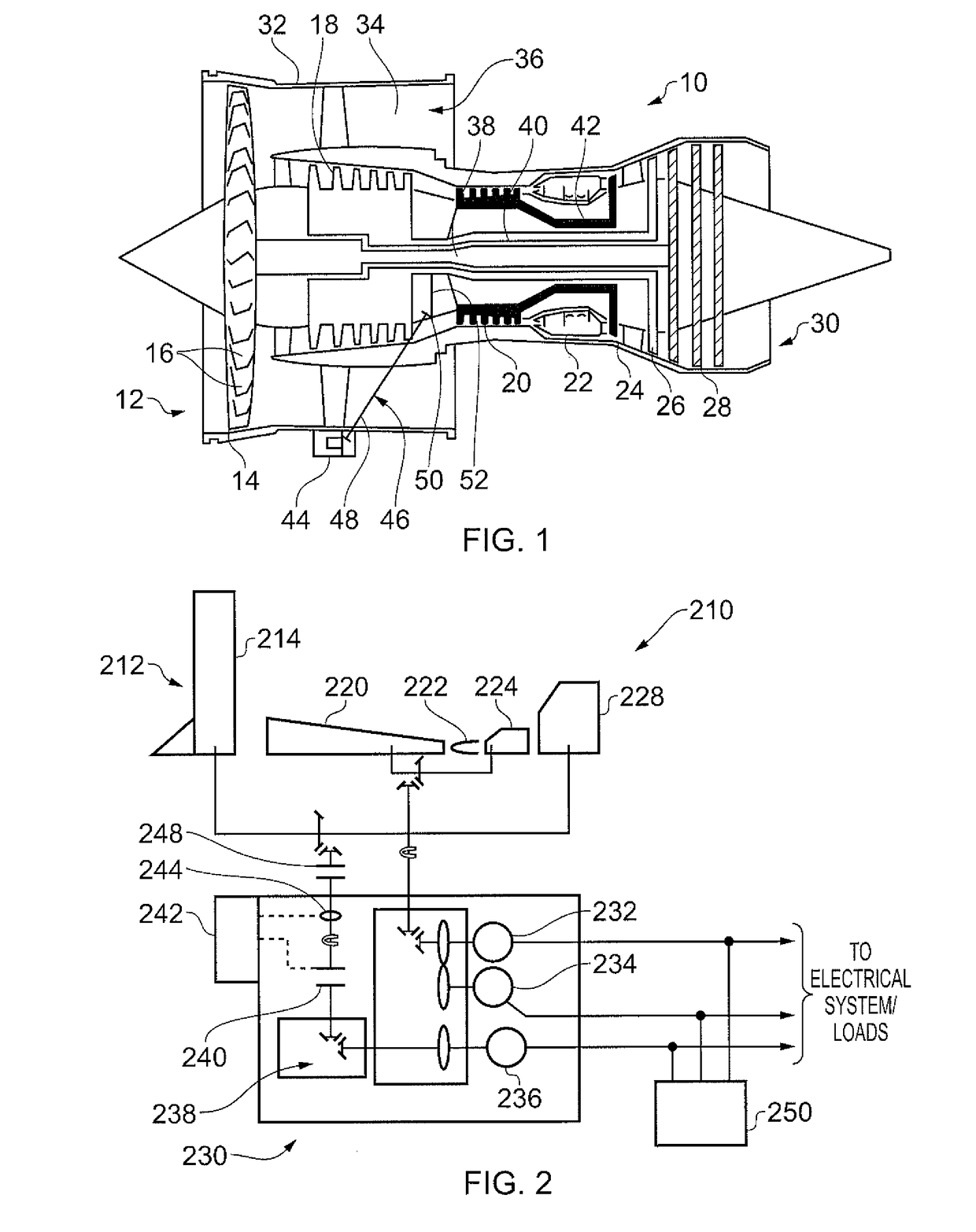
[0029]FIG. 1 shows a conventional ducted fan gas turbine engine 10 comprising, in axial flow series: an air intake 12, a propulsive fan 14 having a plurality of fan blades 16, an intermediate pressure compressor 18, a high-pressure compressor 20, a combustor 22, a high-pressure turbine 24, an intermediate pressure turbine 26, a low-pressure turbine 28 and a core exhaust nozzle 30. A nacelle 32 generally surrounds the engine 10 and defines the intake 12, a bypass duct 34 and a bypass exhaust nozzle 36.

[0030]Air entering the intake 12 is accelerated by the fan 14 to produce a bypass flow and a core flow. The bypass flow travels down the bypass duct 34 and exits the bypass exhaust nozzle 36 to provide the majority of the propulsive thrust produced by the engine 10. The core flow enters in axial flow series the intermediate pressure compressor 18, high pressure compressor 20 and the combustor 22, where fuel is added to the compressed air and the mixture burnt. The hot combustion product...


PUM


Abstract

This invention relates to a multi-spool gas turbine engine, including: a first generator for providing electrical power to an electrical system, the generator being driveably connected to a first spool; a second generator for providing electrical power to the electrical system, the generator being driveably connected to a second spool; a disconnection device for disconnecting the second generator from the second spool; and, a controller configured to selectively operate the disconnection device under predetermined powered engine conditions.

Description

TECHNICAL FIELD OF INVENTION[0001]This invention relates to a gas turbine engine having a plurality of spools which are arranged to drive two or more electrical generators. In particular, this invention is concerned with an arrangement which includes at least one main generator and at least one auxiliary generator which is operable to provide an increased overall efficiency.BACKGROUND OF INVENTION[0002]Conventional gas turbines used for civil aircraft typically have two electrical generators associated with a spool of the engine. The favoured spool by many gas turbine manufacturers and air framers is the high pressure spool because the operating speed range is reduced compared to the lower pressure spools. The reduced speed range is preferable because the electrical frequency outputted by the generators is proportional to spool speed and a large frequency range can be problematic. Also, having a larger speed range generally results in larger, heavier electrical machines.[0003]Some s...

Claims


Application Information

Patent Timeline
Patent Type & Authority Patents(United States)
IPC IPC(8): F01D15/10F02C3/10F02C3/113F02C7/32
CPCF01D15/10F02C3/10F02C7/32F02C3/113Y02T50/672F05D2220/76F05D2260/4023F05D2270/304Y02T50/60
Inventor EDWARDS, HUW LLEWELYNSLATER, ROBERT WILLIAM
Owner ROLLS ROYCE PLC
Why Eureka
Try Eureka