Power factor correction current sense with shunt switching circuit

a switching circuit and current sense technology, applied in power supply testing, instruments, energy industry, etc., can solve the problems of inherently limited efficiency of such configurations, abnormal operation of control circuits, relatively bulky and costly for most practical power converter applications, and achieve the effect of reducing costs

Active Publication Date: 2018-04-10
BEL POWER SOLUTIONS INC
View PDF26 Cites 10 Cited by
  • Summary
  • Abstract
  • Description
  • Claims
  • Application Information

AI Technical Summary

Benefits of technology

[0014]In one aspect, circuitry as disclosed herein may avoid disruptive voltages on the current sense transformer during reverse current flow, which otherwise may

Problems solved by technology

Efficiency for such configurations can be inherently limited, in that there are two diode voltage drops at the input stage and one at the boost stage.
This is problematic for prospective designs, as the efficiency requirements for power converters are constantly being pushed higher and higher.
Current sense transformers are known in the art for sampling current, but in a totem-pole configuration it may be unders

Method used


Image

  • Power factor correction current sense with shunt switching circuit
  • Power factor correction current sense with shunt switching circuit
  • Power factor correction current sense with shunt switching circuit

Examples


Embodiment Construction

[0042]Referring generally to FIGS. 2-15, various exemplary embodiments of an invention may now be described in detail. Where the various figures may describe embodiments sharing various common elements and features with other embodiments, similar elements and features are given the same reference numerals and redundant description thereof may be omitted below.

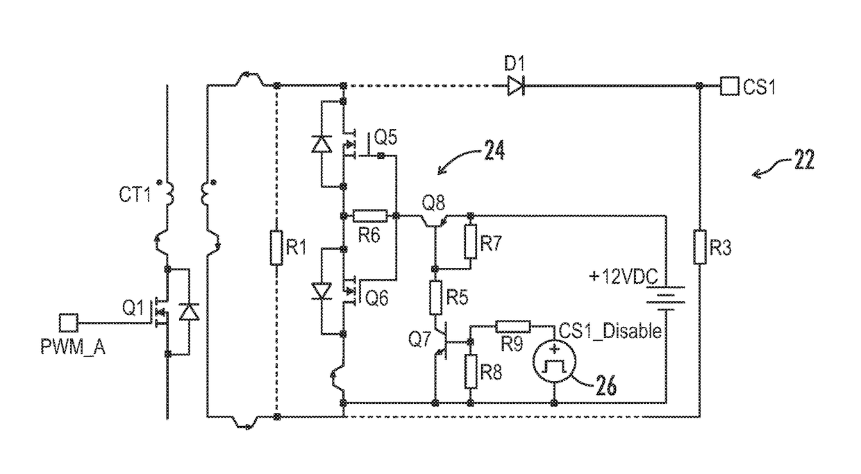
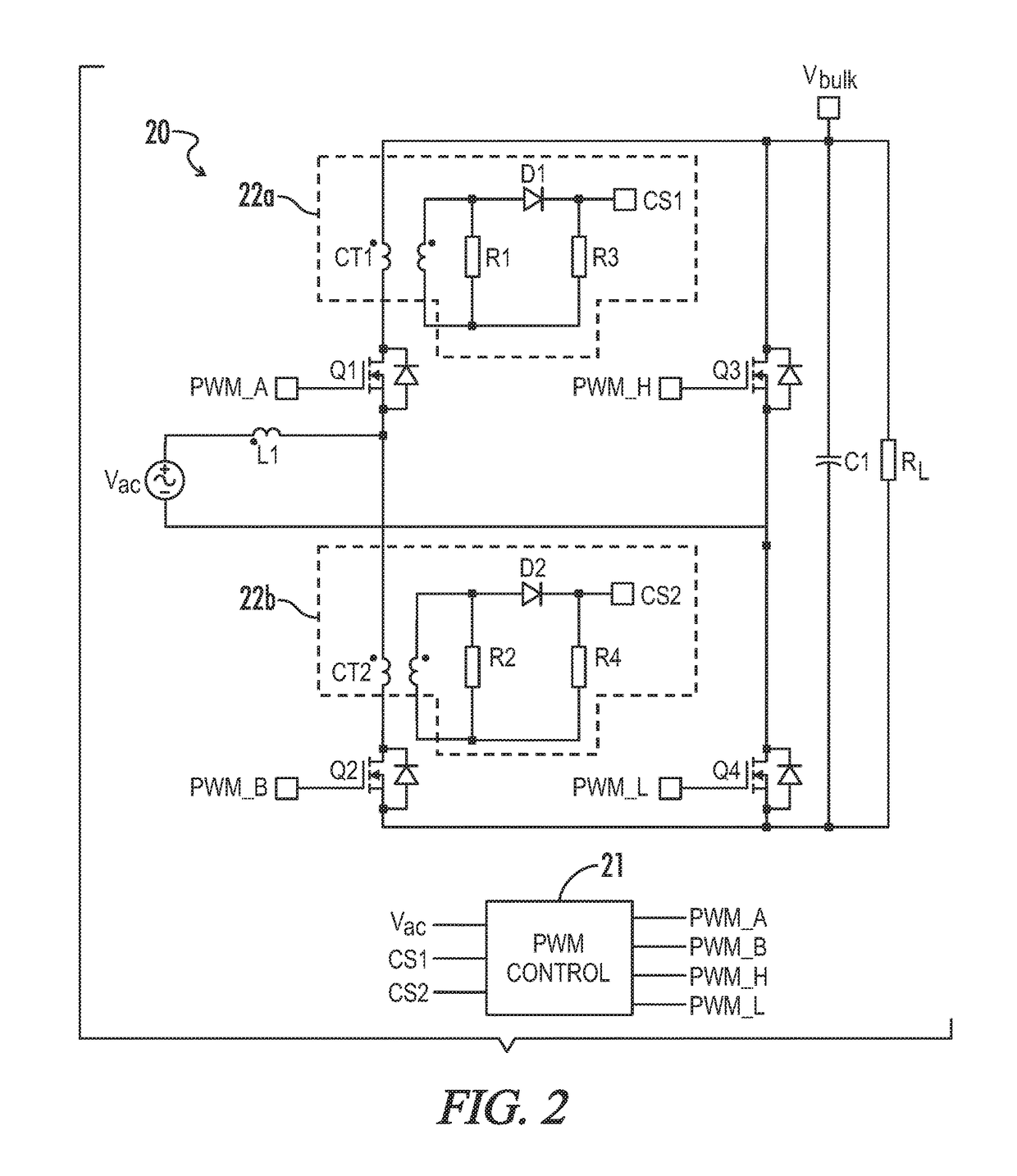
[0043]An exemplary totem-pole PFC converter 20 with current sense transformers 22a, 22b, for feedback of sensed current to a PWM controller 21 may be described with reference to FIG. 2. With further reference to FIG. 3, description may further be provided with respect to the timing of relevant drive signals. In the positive AC line half cycle, switching element Q2 is the active boost switch and switching element Q1 is the freewheeling switch. Switching element Q4 is turned on to complete the circuit return. The current signal through switching element Q2 is transferred to current sense signal CS2 via the current sense transform...


PUM


Abstract

A power converter is provided with a totem-pole power factor correction (PFC) circuit for bridgeless line rectification, and current sensing circuit that can be selectively disabled to reduce unwanted current sense signal components and undesirable current transformer voltage stresses. The totem-pole PFC has at least a first leg with first and second switching elements coupled in series. A PFC inductor is coupled between an AC input on a first end and a node between the switching elements. The current sensing circuit includes a first transformer winding coupled in series with the first switching element, a second transformer winding magnetically coupled to the first winding and configured to deliver current from the first winding to a current sense terminal during an active phase for the first switching element, and a shunt circuit configured to disable the current sensing circuit during a freewheeling phase for the first switching element.

Description

CROSS-REFERENCES TO RELATED APPLICATIONS[0001]This application claims benefit of U.S. Provisional Patent Application No. 62 / 249,488, filed Nov. 2, 2015, and which is hereby incorporated by reference.[0002]A portion of the disclosure of this patent document contains material that is subject to copyright protection. The copyright owner has no objection to the reproduction of the patent document or the patent disclosure, as it appears in the U.S. Patent and Trademark Office patent file or records, but otherwise reserves all copyright rights whatsoever.STATEMENT REGARDING FEDERALLY SPONSORED RESEARCH OR DEVELOPMENT[0003]Not ApplicableREFERENCE TO SEQUENCE LISTING OR COMPUTER PROGRAM LISTING APPENDIX[0004]Not ApplicableBACKGROUND OF THE INVENTION[0005]The present invention relates generally to power factor correction (“PFC”) circuits. More particularly, the present invention relates to totem-pole PFC circuits implementing current sense transformers and shunt circuitry to prevent damage f...

Claims


Application Information

Patent Timeline
IPC IPC(8): H02M1/42G01R15/18H02M1/00
CPCH02M1/4208G01R15/183H02M2001/0009H02M1/4233G01R31/40G01R21/006Y02B70/10Y02P80/10H02M1/0009
Inventor LI, JUNTAN, VIM
Owner BEL POWER SOLUTIONS INC
Why Eureka
Try Eureka