Water pipe wrench structure

a technology of wrenches and pipes, applied in the field of water pipe wrenches, can solve the problems of reducing the opening up width of wrenches and inconvenience during use, and achieve the effects of convenient connection, convenient and fast assembly operation, and high structural strength

Active Publication Date: 2018-04-17
CHEN JIN FU
View PDF5 Cites 9 Cited by
  • Summary
  • Abstract
  • Description
  • Claims
  • Application Information

AI Technical Summary

Benefits of technology

[0007]The main purpose of the present invention is to provide a water pipe wrench structure, which comprises a wrench body having a tooth space and a side edge that has a curved shape so as to enable another wrench body to open up with a larger width, and thus enhance the operability and convenience during use.
[0017]1. First, the two wrench bodies can be manufactured with the path of forging flow line towards the direction of holding, and using the bridge joint component, the first and the second wrench bodies can be intersected and pin jointed at one point, and a hole with a passage to the first wrench body is not required to be opened on the second wrench body; and therefore, the first and second wrench bodies can have relatively higher structural strength, and also the first and second wrench bodies can be readily connected via the bridge joint component during assembly, which would make the assembly operation more convenient and quicker.
[0018]2. The two ends of said flexible component can have shapes with different sectional areas, for instance a conical shape, which would enable better mounting of the flexible component on the stepped surface, or in other words, when the stepped surface part is narrowed down, said conical flexible component can appropriately be fitted and mounted on the stepped surface, which accordingly improves the convenience in assembly.
[0019]3. Said angle restriction body (grinding tooth piece, base plate) is manufactured by forging / metal injection, and the forging / metal injection method enables the metal to take the desired shape effectively while retaining the strength of the metal, as well as changing or adjusting the direction of metal flow line has more consistency, and also retains the clamping strength and durability of the grinding tooth piece.

Problems solved by technology

However, the side face 42 of the wrench body 4 also corresponds to the shape of said tooth space 41 and forms a long straight shape, and this structural shape reduces the opening up width of the wrench body 5 during the opening up motion, which leads to inconvenience during use.

Method used


Image

  • Water pipe wrench structure
  • Water pipe wrench structure
  • Water pipe wrench structure

Examples


Embodiment Construction

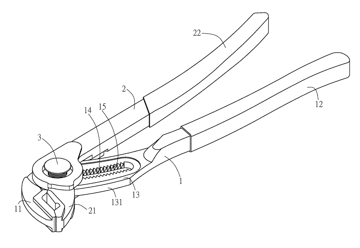
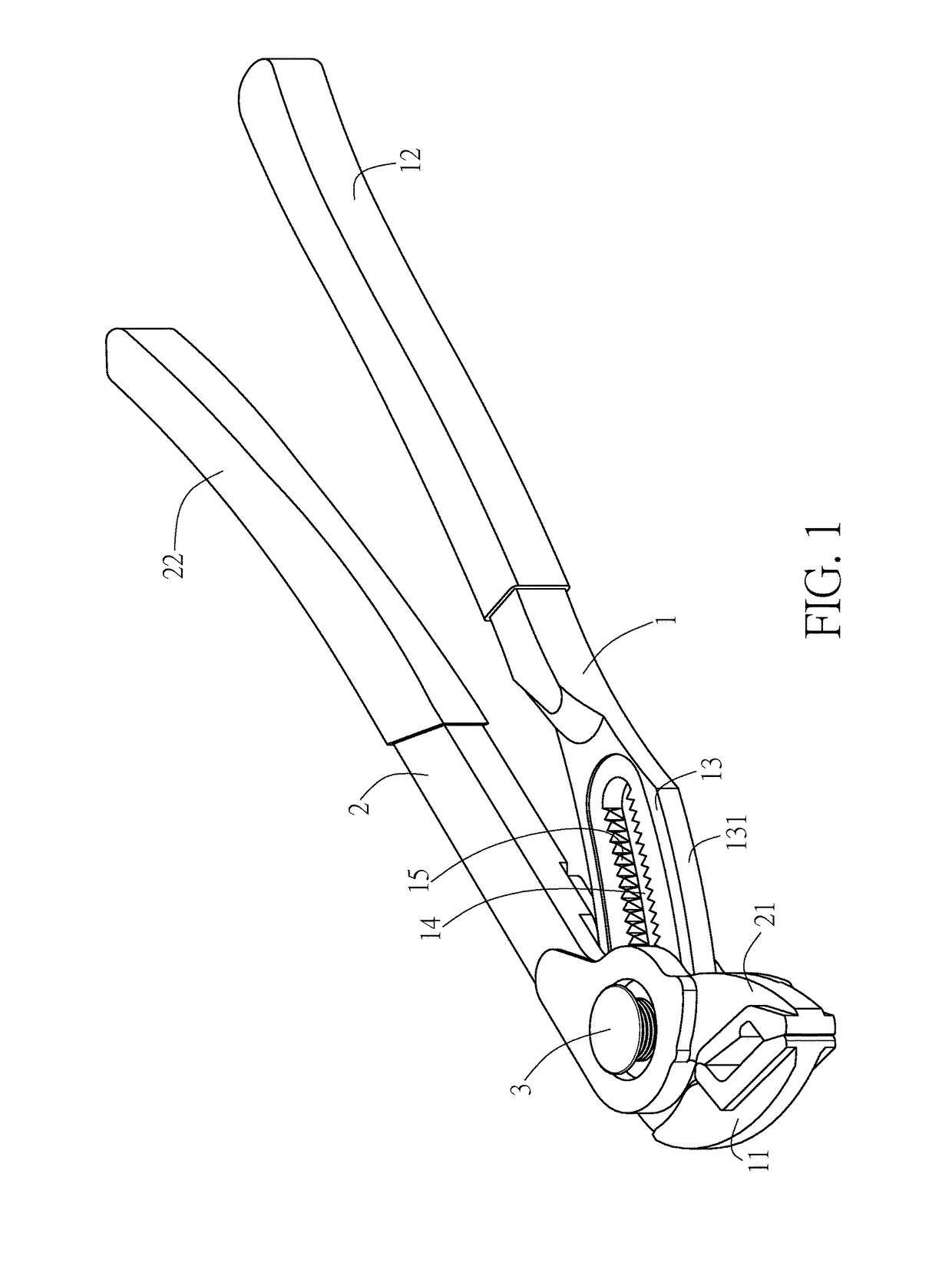
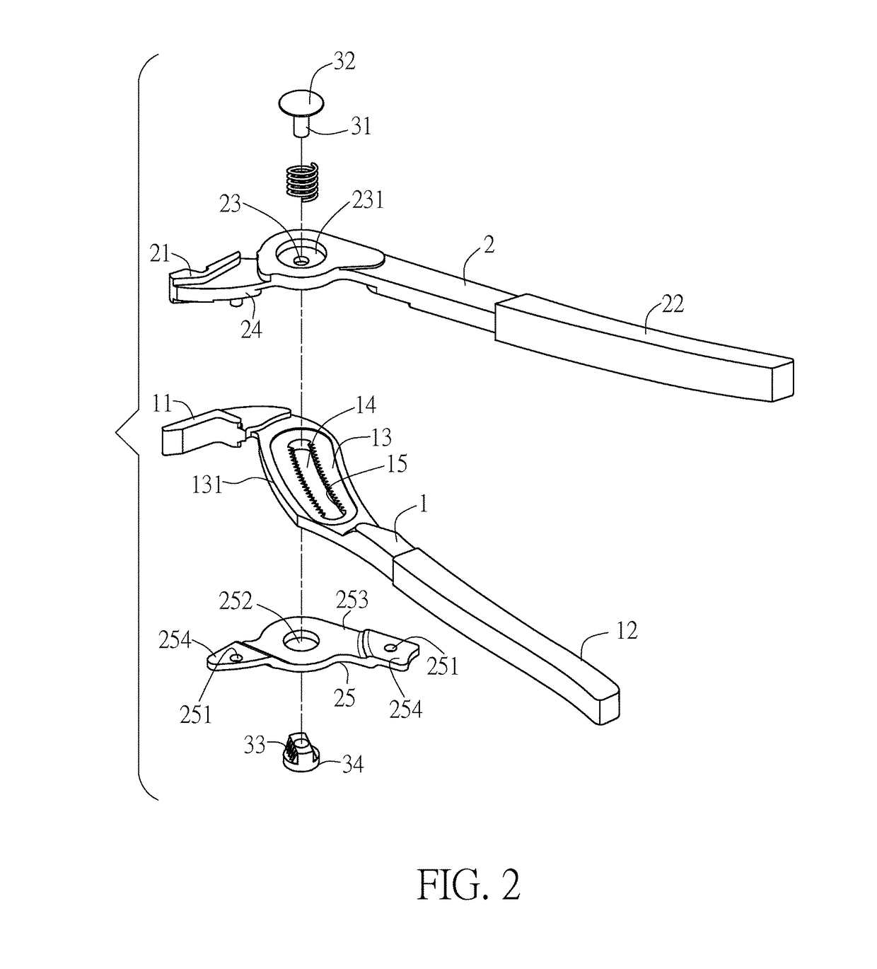
[0030]In FIGS. 1 to 3, the water pipe wrench structure of the present invention is shown, which mainly comprises a first wrench body 1, a second wrench body 2, and a control component 3. Among these, said first wrench body 1 has a first clamping piece 11 and a first handle piece 12 on its two ends, respectively; and said second wrench body 2 has a second clamping piece 21 and a second handle piece 22 on its two ends, respectively. Moreover, the forging flow line of the above said wrench bodies 1, 2 extends along the extension direction of the wrench bodies 1, 2 as shown in FIGS. 4 and 5, and as a result increases the tensile strength of the two wrench bodies 1, 2 in this direction.

[0031]Accordingly, said first wrench body 1 comprises an actuating piece 13 between said first clamping piece 11 and said first handle piece 12, and said actuating piece 13 comprises a penetrating tooth space 14. Said tooth space 14 comprises a plurality of teeth 15 separately on the left and right sides. ...


PUM


Abstract

A water pipe wrench structure consisting of a first wrench body and a second wrench body pin jointed by a control component. The first wrench body includes an actuating piece. A tooth space is positioned on this actuating piece. This actuating piece and a tooth piece extend with a uniform curvature. The second wrench body includes a perforation to pass the control component through this perforation and the tooth space. This control component includes a column piece and a grinding tooth piece, and the grinding tooth piece can be moved by pressure, so that the grinding tooth piece can be engaged to or separated from the tooth space and thus end the movement of the control component.

Description

BACKGROUND OF THE INVENTION[0001]Field of the Invention[0002]The present invention relates to water pipe wrench structures, particularly to a water pipe wrench with adjustable clamping diameter.[0003]Description of the Related Art[0004]Conventional water pipe wrenches, such as the ones shown in FIGS. 10 and 11 are formed of two wrench bodies 4, 5 hinged at an intersection point. Among these, a long straight tooth space 41 is found on one of the wrench bodies 4, and the other wrench body 5 is positioned in said tooth space 41 via a pivot 51 comprising ratchets 52; wherein said pivot 51 can be controlled so as to be separated from said tooth space 41, so that the wrench body 5 can make a sliding movement relative to the opposite wrench body 4, and in this way adjust the clamping diameter of the water pipe wrench. Afterwards, said pivot 51 can again be controlled to engage the ratchet 52 into the tooth space 41, so that the position of said pivot 51 would be fixed, and the clamping dia...

Claims


Application Information

Patent Timeline
Patent Type & Authority Patents(United States)
IPC IPC(8): B25B7/10
CPCB25B7/10
Inventor CHEN, JIN FU
Owner CHEN JIN FU
Why Eureka
Try Eureka