Beam branching device
a beam branching and beam technology, applied in the field of beam branching devices, can solve the problems of substantially impossible to switch an optical path at a high speed, increase in the size and weight of inability to satisfy the suppression of an increase in the cost, the size and the like of the beam branching device, so as to reduce the size and weight of the optical path switching device, and suppress an increase in the cost, the effect of increasing coupling efficiency
- Summary
- Abstract
- Description
- Claims
- Application Information
AI Technical Summary
Benefits of technology
Problems solved by technology
Method used
Image
Examples
first embodiment
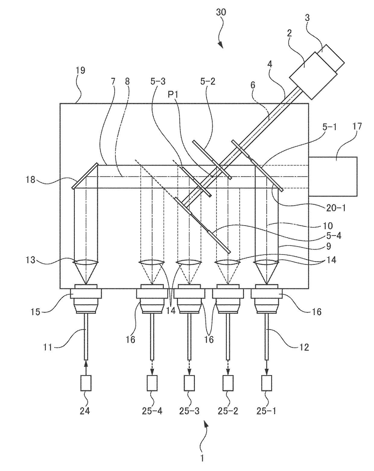
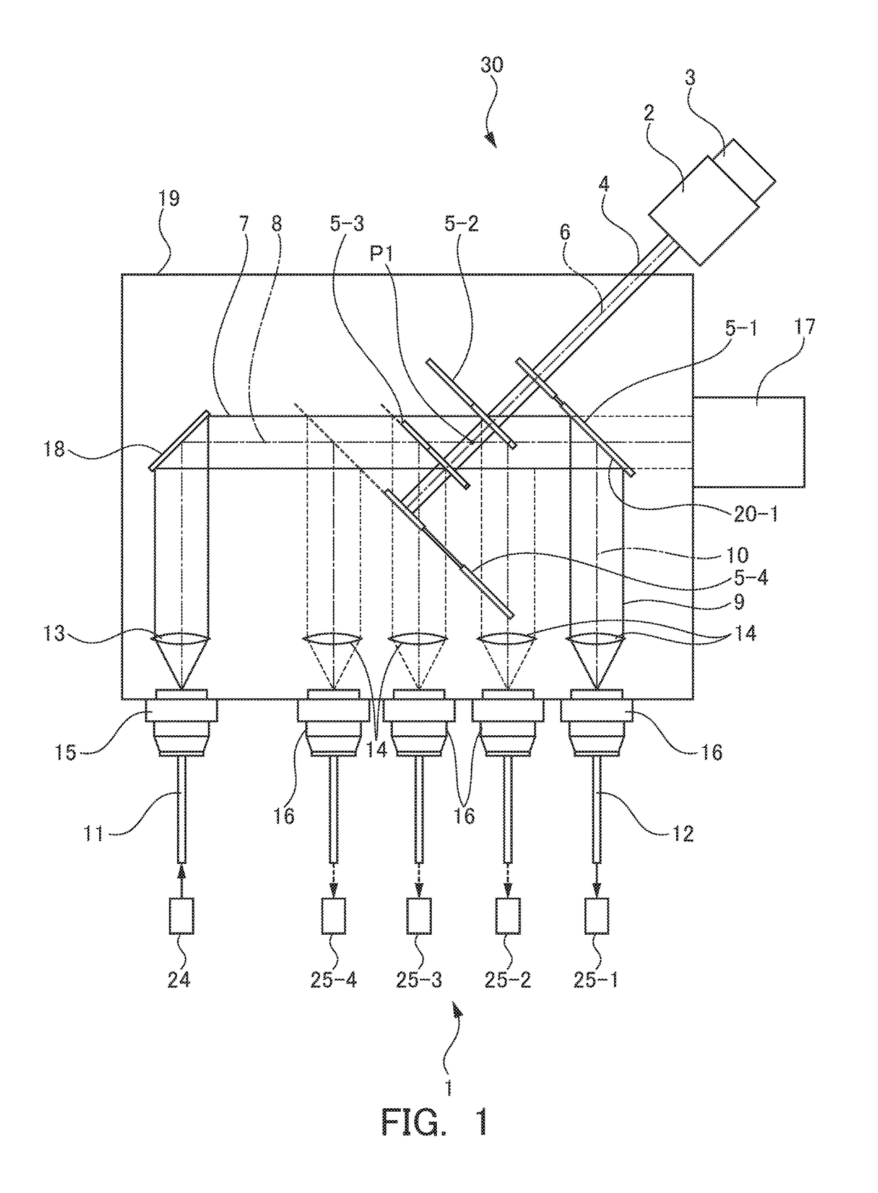
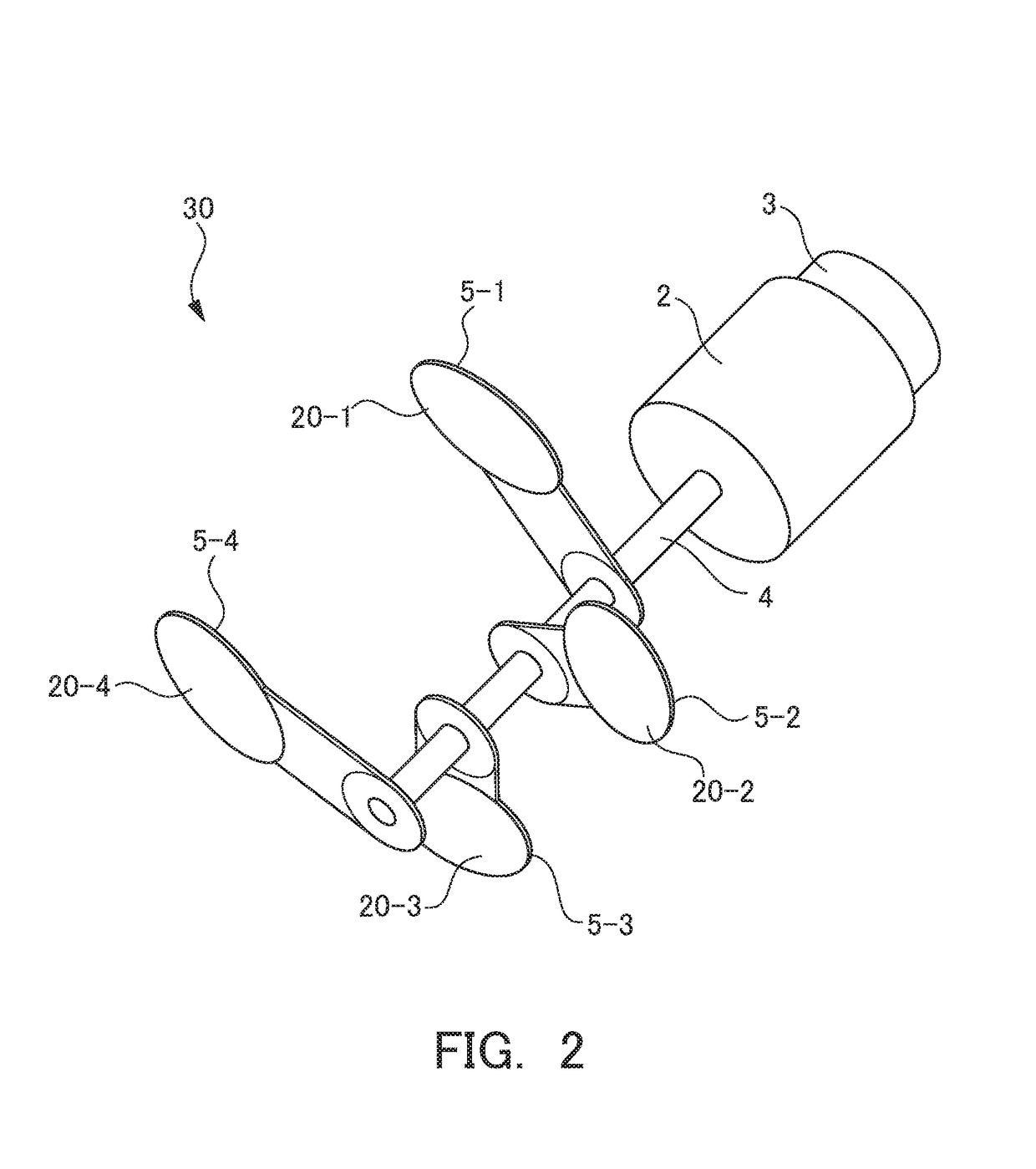
[0072]FIG. 1 is a diagram illustrating a configuration of a beam branching device according to a first embodiment of the present invention. FIG. 2 is a perspective view illustrating an optical-path-switching optical system of the beam branching device according to the first embodiment of the present invention.
[0073]As illustrated in FIGS. 1 and 2, a beam branching device 1 branches a laser beam emitted from a laser apparatus 24 into a plurality of (in the present embodiment, five) directions and supplies the laser beam to a plurality of (in the present embodiment, four) machining heads 25 (first, second, third, and fourth machining heads 25-1, 25-2, 25-3, and 25-4). This beam branching device 1 has one optical-path-switching optical system 30, and this optical-path-switching optical system 30 includes a rotary motor 2, a cylindrical rotating member 4, a plurality of (in the present embodiment, four) reflection mirrors 5 (first, second, third, and fourth reflection mirrors 5-1, 5-2, ...
second embodiment
[0101]FIG. 9 is a diagram illustrating a configuration of a beam branching device according to a second embodiment of the present invention.
[0102]A beam branching device 21 is different from that of the first embodiment (FIG. 1) in that as illustrated in FIG. 9, the fixed reflection mirror 18 that reflects the incident beam 7 is omitted, and instead of this, four fixed reflection mirrors 28 that reflect branched reflection beams 9 are provided and all connectors 15 and 16 are attached to the same surface (the left side surface in FIG. 9) of the housing 19. The other components are basically similar to those of the first embodiment.
[0103]Therefore, the second embodiment provides the same operational effects as those of the first embodiment. In addition to this, in the second embodiment, the positions (the distance to the optical-path-switching optical system 30 in the vertical direction of FIG. 9) of the four fixed reflection mirrors 28 are set appropriately so that the interval betw...
third embodiment
[0105]FIG. 10 is a diagram illustrating a configuration of a beam branching device according to a third embodiment of the present invention.
[0106]A beam branching device 31 is different from that of the first embodiment (FIG. 1) in that as illustrated in FIG. 10, the number of reflection mirrors 5 attached to the rotating member 4 is reduced from 4 to 2, and the number of branching directions is changed from 5 to 3. Due to this, the reflection mirror surface portions 20 of the two reflection mirrors 5 are arranged at different angles about the central axis 6 of the rotating member 4. The other components are basically similar to those of the first embodiment.
[0107]Since the beam branching device 31 has the above-described configuration, when a laser beam is supplied from the laser apparatus 24 to an arbitrary machining head 25 using the beam branching device 31 to perform laser machining, the optical path of the reflection beam 9 is switched according to the following procedure.
[010...
PUM
| Property | Measurement | Unit |
|---|---|---|
| intersection angle | aaaaa | aaaaa |
| diameter | aaaaa | aaaaa |
| virtual intersection angle | aaaaa | aaaaa |
Abstract
Description
Claims
Application Information
 - R&D
- Intellectual Property
- Life Sciences
- Materials
- Tech Scout
- Unparalleled Data Quality
- Higher Quality Content
- 60% Fewer Hallucinations
Browse by: Latest US Patents, China's latest patents, Technical Efficacy Thesaurus, Application Domain, Technology Topic, Popular Technical Reports.
© 2025 PatSnap. All rights reserved.Legal|Privacy policy|Modern Slavery Act Transparency Statement|Sitemap|About US| Contact US: help@patsnap.com


