Resonant converter and switching power supply device

a switching power supply and resonance converter technology, applied in the direction of electric variable regulation, process and machine control, instruments, etc., can solve the problems of difficult control of pwm control and high frequency on-time control, and achieve the effect of reducing the operating voltage of the switch elemen

Active Publication Date: 2018-04-17
TDK CORPARATION
View PDF33 Cites 42 Cited by
  • Summary
  • Abstract
  • Description
  • Claims
  • Application Information

AI Technical Summary

Benefits of technology

[0005]The present invention has been made in view of the above-described issues of the related art, and there is provided a reliable resonant converter and switching power supply device in which the operating voltage of switch elements is decreased without affecting the life of the switches as much as possible and for which switch elements capable of withstanding an operating voltage of about 600 V can be selected.
[0006]In order to address the above-described issues, a resonant converter according to the present invention includes a step-down converter and a resonant inverter. The step-down converter includes at least two switch elements, and a first coil connected to the at least two switch elements. The resonant inverter includes a first switch element and a second switch element that are alternately turned on and off, a first capacitor and a second capacitor connected in parallel to the first switch element and the second switch element respectively, a first inverter section constituted by the first switch element and the first capacitor, and a second inverter section constituted by the second switch element and the second capacitor. The first inverter section includes a first resonant circuit constituted by the first coil and the first capacitor, and the second inverter section includes a second resonant circuit constituted by the first coil and the second capacitor. As a consequence, the operating voltage of the switch elements can be decreased.
[0007]In the resonant converter described above, the first inverter section may further include a third resonant circuit, and the second inverter section may further include a fourth resonant circuit. As a consequence, the input voltage of the resonant inverter can be decreased, and the operating voltage of the switch elements can be decreased accordingly.

Problems solved by technology

This patent literature discloses a technique in which burst control is used for a converter operating at a high frequency because it is difficult to perform PWM control on such a converter.
However, in the inverter as described in U.S. Pat. No. 5,600,547 or in U.S. Pat. No. 8,400,788, the step-down converter is controlled by performing PWM control, and therefor, it is difficult to control the on-time at a high frequency.

Method used


Image

  • Resonant converter and switching power supply device
  • Resonant converter and switching power supply device
  • Resonant converter and switching power supply device

Examples


first embodiment

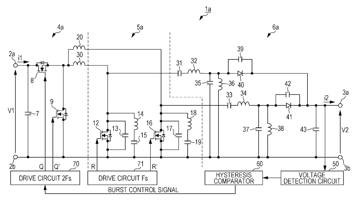
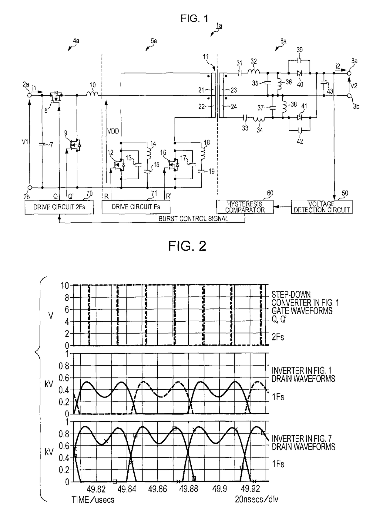
[0026]FIG. 1 is a circuit diagram illustrating a configuration of a switching power supply device 1a according to an embodiment of the present invention. The resonant converter 1a illustrated in FIG. 1, which is one exemplary embodiment of a switching power supply device, includes a pair of input terminals, namely, a first input terminal 2a and a second input terminal 2b (hereinafter also collectively referred to as input terminals 2 unless specifically referred to otherwise), a pair of output terminals, namely, a first output terminal 3a and a second output terminal 3b (hereinafter also collectively referred to as output terminals 3 unless specifically referred to otherwise), a step-down converter 4a, a resonant inverter 5a, and a resonant rectifier 6a. The switching power supply device 1a converts an input voltage (DC voltage) V1 input to the input terminals 2 into an output voltage (DC voltage) V2 and outputs the output voltage V2 from the output terminals 3. In the switching pow...

second embodiment

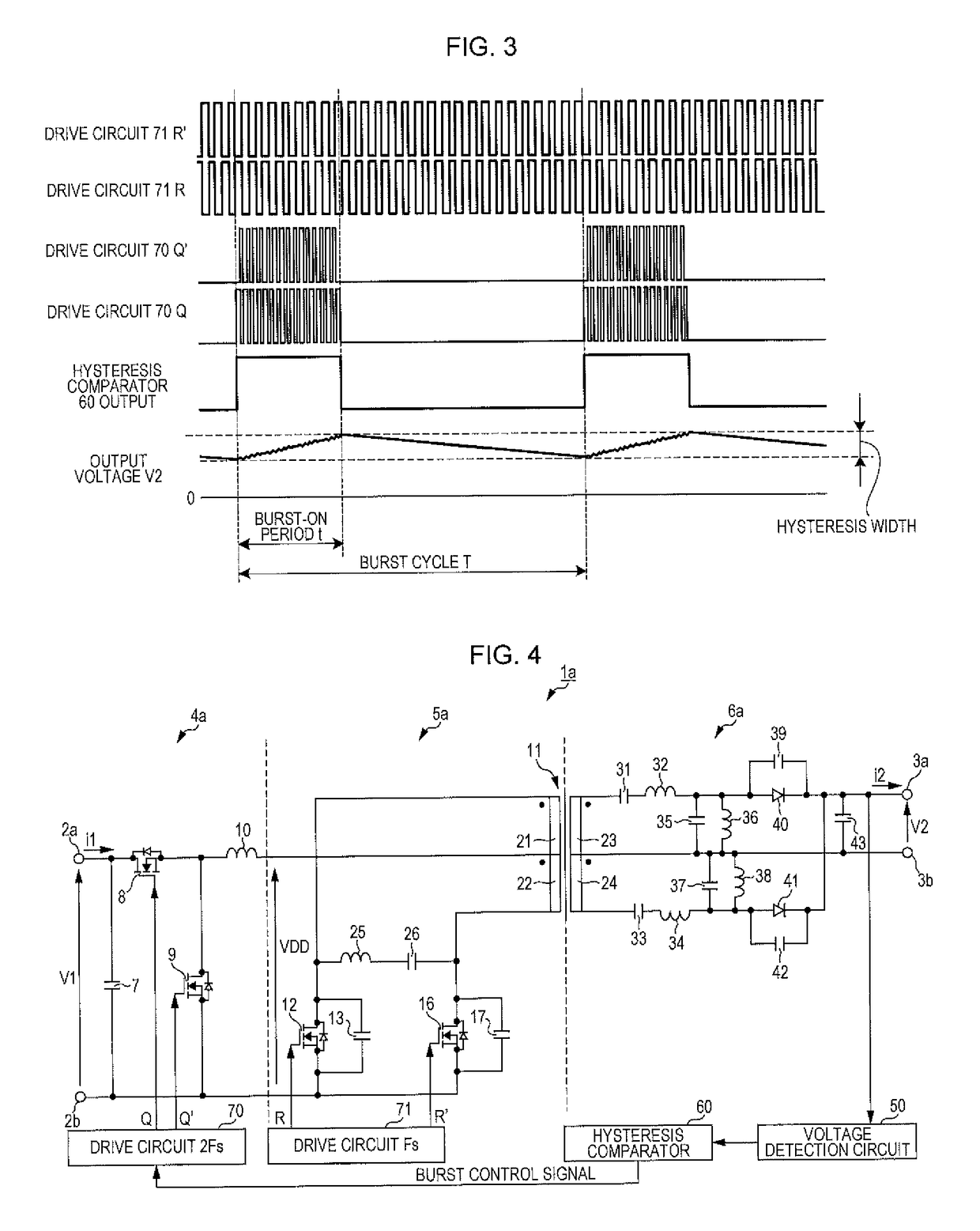
[0035]FIG. 4 is a circuit diagram illustrating a configuration of the switching power supply device 1a according to a second embodiment of the present invention. The second embodiment is different from the first embodiment in that the third and fourth resonant circuits that constitute the resonant inverter 5a are replaced by a fifth resonant circuit that is shared by the inverter sections. Specifically, the second choke coil 14, the third resonant capacitor 15, the fourth choke coil 18, and the fourth resonant capacitor 19 illustrated in FIG. 1 are replace by a series connection of a fifth resonant coil 25 and a fifth resonant capacitor 26 placed between the drain terminal of the switch element 12 and the drain terminal of the switch element 16. The fifth resonant coil 25 and the fifth resonant capacitor 26 constitute the fifth resonant circuit. The rest of the configuration is the same as in the first embodiment. By driving the step-down converter 4a in accordance with burst contro...

third embodiment

[0036]FIG. 5 is a circuit diagram illustrating a configuration of the switching power supply device 1a according to a third embodiment of the present invention. The third embodiment is different from the first embodiment in that the transformer 11 is not placed between the resonant inverter 5a and the resonant rectifier 6a but is placed in the resonant rectifier 6a. Further, two resonant coils, that replace the first resonant coil 10 are provided. The circuit configuration is described below.

[0037]The step-down converter 4a includes the input capacitor 7, the switch element 8, and the switch element 9. The drain terminal of the switch element 8 is connected to the first input terminal 2a and to the input capacitor 7, and the source terminal of the switch element 8 is connected to one end of the sixth resonant coil 30, to one end of the seventh resonant coil 20, and to the drain terminal of the switch element 9. The source terminal of the switch element 9 is connected to the input ca...


PUM


Abstract

A resonant inverter includes a first switch element and a second switch element that are alternately turned on and off, a first capacitor and a second capacitor, a first inverter section constituted by the first switch element and the first capacitor, and a second inverter section constituted by the second switch element and the second capacitor. A first coil and the first capacitor constitute a first resonant circuit included in the first inverter section, and the first coil and the second capacitor constitute a second resonant circuit included in the second inverter section, thereby forming a resonant converter.

Description

BACKGROUND OF THE INVENTION1. Field of the Invention[0001]The present invention relates to a resonant converter and a switching power supply device in which the operating voltage of switch elements included therein can be easily decreased.2. Description of the Related Art[0002]U.S. Pat. No. 5,600,547 discloses a step-down converter and a push-pull inverter coupled together as a constant-current control circuit for a backlight and also discloses a method in which the output voltage of the step-down converter is controlled by a pulse width modulation (PWM) circuit in accordance with the output current to thereby control the output current (see FIG. 8). In the disclosed method, switches in the push-pull inverter unit are alternately turned on and off with a phase difference of 180 degrees, and the push-pull inverter is not controlled. The output current is detected by a resistor as a voltage and is thereafter compared by an error amplifier. The output from the error amplifier is compar...

Claims


Application Information

Patent Timeline
Patent Type & Authority Patents(United States)
IPC IPC(8): H02M3/158H02M3/335H02M3/337H02M7/48H02M1/00
CPCH02M3/337H02M3/158H02M2001/007Y02B70/1491Y02B70/1425Y02B70/1433H02M2001/0058Y02B70/10Y02P80/10H02M1/0058H02M1/007H02M3/01
Inventor IMAI, KATSUNORI
Owner TDK CORPARATION
Why Eureka
Try Eureka