Apparatus and method for making atomic layer deposition on fine powders

a technology of atomic layer and fine powder, which is applied in the direction of chemical vapor deposition coating, transporting and packaging, coating, etc., can solve the problems of non-ald depositon, filter blockage, and large waste of carrier gases, so as to improve the agitation of powder and improve the agitation speed. , the effect of rotation speed

Inactive Publication Date: 2018-04-24
JIANG YING BING +1
View PDF46 Cites 11 Cited by
  • Summary
  • Abstract
  • Description
  • Claims
  • Application Information

AI Technical Summary

Benefits of technology

[0014]In one aspect of the embodiment of this invention, a rotary vessel is used as the container of the powdered samples, and the powders are agitated by the rotary movement so as to improve the efficacy of “precursor-exposure” and “purge” steps.
[0020]In another aspect of the embodiments of this invention, to reduce the “maximum height that powders can reach”, the agitation of powders caused by the gas flow must be minimized. To minimize the agitation caused by the gas flow during pulsed precursor introduction, the configuration of the gas injection port must be carefully designed. A “gas flow diffuser” can be installed at the gas injection port to slow down the gas flow velocity and enable the gas(es) to enter the ALD chamber in a smooth and gentle manner.
[0021]Besides the use of such a “gas flow diffuser”, the mode of introducing precursor gases can also be carefully controlled (e.g., using a computer or controller). For example, the valve controlling precursor dosage can be opened briefly so that each time there is only a small amount of precursor gas introduced to the ALD chamber, and the amount is small enough so that it cannot cause a big agitation of the powders. And for each precursor exposure step, the valve can be opened briefly for multiple times to achieve enough precursors for the exposure.
[0022]To reduce the “maximum height that most powders can reach”, agitations caused by gas flow shall be minimized. For this reason, the pumping speed can be low at the beginning when the gas pressure is relatively high in the ALD deposition chamber; as gas pressure reduces, higher pumping speed can be used. Therefore, a valve with variable pumping speed can be used, or multiple pumping pathways with different pumping speeds can be used either in the main pumping line or in the ALD chamber so that the pumping speed can be adjusted by using different pathway or different combination of the pathways for pumping.
[0024]To enhance the powder agitation by rotary motion, the rotation speed can be non-constant, and the rotation can even be intermittent. To further enhance the powder agitation, small glass or ceramic beads or similar materials can be mixed with the powders during ALD.
[0025]In the other aspect of the embodiments of this invention, in the rotary powder-ALD system, the rotatable chamber is designed to be of low-cost, and be connected to the main ALD system via fast connections such as KF flanges, so that the chamber part can be removed from the main system conveniently for easy replacement / exchange or cleaning. The “low-cost” and “easy to replace / exchange” features make it possible for users to have a series of ALD chambers so that each chamber can be assigned to one specific sample, thereby avoiding inter-sample contaminations.

Problems solved by technology

However, when running ALD on small particles, or powdered materials, there are at least three issues: 1) for a plurality of powders, the powders buried at the bottom have less chance to be exposed to the reactant gases, causing problem for “precursor-exposure” step; 2) the gas molecules trapped in between of powders at the bottom have a less chance to be pumped or purged away, causing problem for “purge” step, resulting in non-ALD depositon in these locations; 3) the powders are light and can be easily blown away by the gas flow during the steps of introducing precursors for “precursor-exposure” and the step of pumping for “purge”, making powders being carried by gas flow thereby sticking on the chamber walls, or entering the pumping port as mentioned in paragraph .
But there are several disadvantages in this approach: 1) the ALD chamber has to be relatively large to satisfy the configuration of a “fluidized bed”, e.g. several feet in height, especially when less reactive precursors are used and longer residence time is needed to complete the reaction; 2) fluidized bed also requires relatively high gas pressure and large gas flow so that the particles can be blown up by the gas flows which causes a big waste of carrier gases; 3) powders will fly around vigorously inside the chamber, and a porous filter with small pores has to be used to prevent powders from being pumped away, but this porous filter will trap powders no that many powders are wasted by being trapped inside the pores.
Further, once the powders are trapped inside the pores, the filter will be blocked.
As a consequence, the filter has to be cleaned or replaced frequently; 4) since powders will fly around inside the chamber, many powders will stick on the chamber walls or be trapped in the porous filters, which are hard to collect after ALD, causing waste of powders and contamination for the following ALD process.
Therefore, for this fluidized-bed ALD system, it is hard to process a very small amount of powder due to loss of powders in the filter and the chamber walls.
It doesn't work very well if research-scale small amount of powdered samples are processed.
Again, the porous filter will trap powders and may be blocked by the powders after long-term usage.

Method used


Image

  • Apparatus and method for making atomic layer deposition on fine powders
  • Apparatus and method for making atomic layer deposition on fine powders
  • Apparatus and method for making atomic layer deposition on fine powders

Examples


Embodiment Construction

[0035]It is to be understood that the appended drawings and the exemplary embodiments hereafter illustrate only typical embodiments of this invention and are therefore not to be considered limiting of its scope, as the invention may admit to other equally effective embodiments.

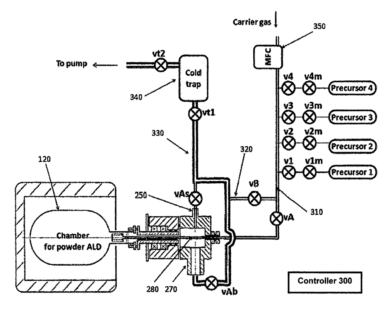
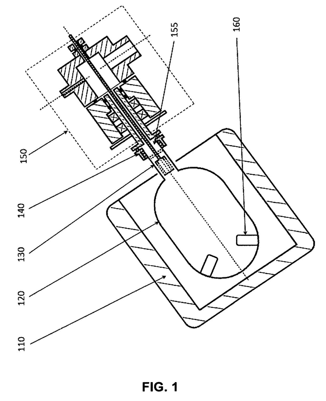
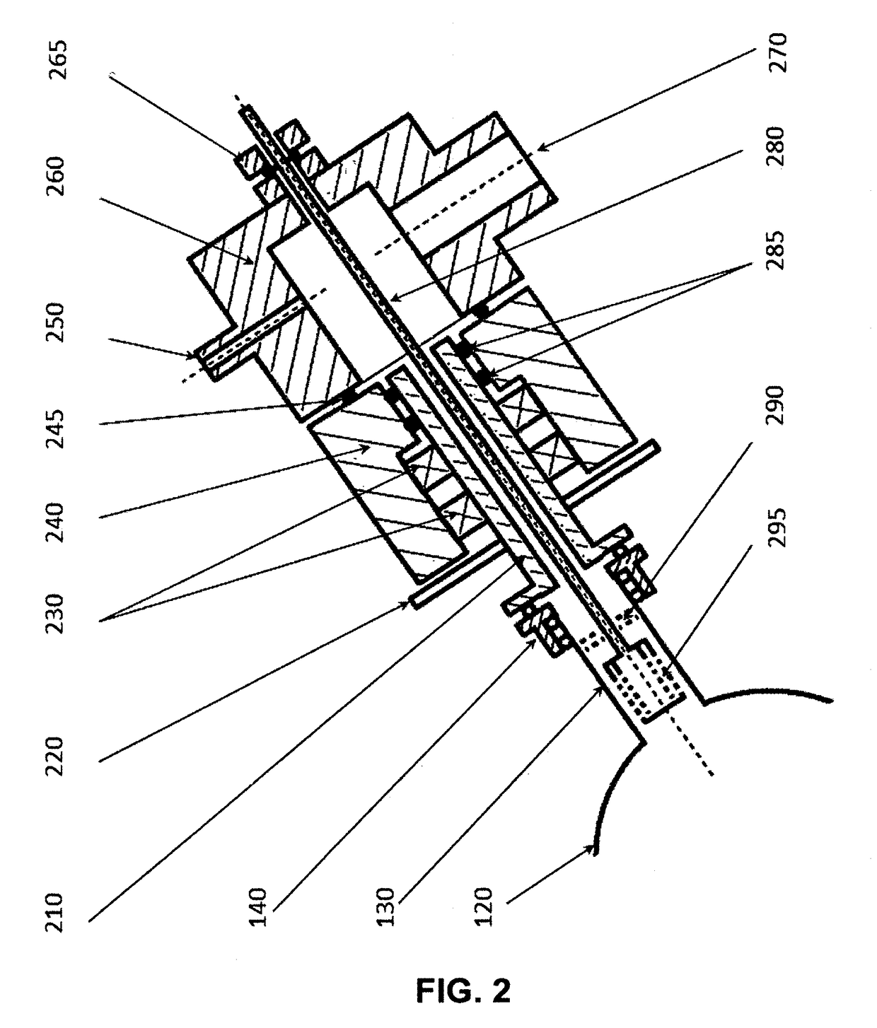
[0036]In one aspect of the embodiments of this invention, a rotary vessel is used to hold powders, and the powders are agitated by the rotary movement so as to improve the efficacy of “precursor-exposure” and “purge” steps. In addition, instead of relying on using porous filtering to confine the powders within the chamber, mechanism is provided so that the gravity of the powders can be employed to confine the powders within the chamber as gravity tends to pull the powders down to the bottom of the chamber. To facilitate this mechanism and prevent powders from being carried by gas flow and entering the pumping port, the ALD chamber shall be configured in a way so that the opening of the ALD chamber (which is th...


PUM

PropertyMeasurementUnit
angleaaaaaaaaaa
angleaaaaaaaaaa
diameteraaaaaaaaaa

Abstract

Method and apparatus for making atomic layer deposition on powdered materials are provided. A rotary vessel with tilted rotation axis can be used as the deposition chamber. The rotary vessel can be directly used as the deposition chamber, or the rotary vessel is positioned inside a vacuum chamber that serves as the deposition chamber. A hallow shaft can be used to deliver rotary motion and facilitate pumping. A tube can be inserted into the hollow shaft or the rotary vessel to introduce precursors. Gas diffuser and slowly increased pumping speed can be used to reduce the agitation caused by gas flow. Intermittent rotation, variable rotary speed, extruding structures on inner surface of the rotary vessel, and the addition of easy-to-agitate powder or beads of other materials can be used to enhance the powder agitation caused by rotation.

Description

CROSS-REFERENCE TO RELATED APPLICATIONS[0001]The present invention relates generally to making coatings or surface modifications on powdered materials (including small fibers). More particularly, the present invention relates to an improved apparatus for making coatings or surface modifications on powdered materials via a deposition process using sequential precursor exposures, for example, the so-called atomic layer deposition (ALD) process.FIELD OF THE INVENTION[0002]The present invention relates generally to making coatings or surface modifications on powdered materials (including small fibers). More particularly, the present invention relates to an improved method and apparatus for making coatings or surface modifications on powdered materials via a deposition process using sequential precursor exposures, for example, the so-called atomic layer deposition (ALD) process.BACKGROUND OF THE INVENTION[0003]Atomic Layer deposition (ALD) process is a layer-by-layer deposition process c...

Claims


Application Information

Patent Timeline
Patent Type & Authority Patents(United States)
IPC IPC(8): C23C16/44C23C16/455C04B35/622
CPCC23C16/4417C04B35/62222C23C16/4412C23C16/45555C23C16/45561C23C16/45544Y10T428/2982
Inventor JIANG, YING-BINGZHANG, HONGXIA
Owner JIANG YING BING
Why Eureka
Try Eureka