Method and apparatus for calibrating a color measurement instrument

a color measurement and instrument technology, applied in the field of color measurement, can solve the problems of difficulty in designing color measurement instruments, and achieve the effect of minimizing differences and minimizing differences

Active Publication Date: 2018-04-24
DATACOLOR
View PDF6 Cites 6 Cited by
  • Summary
  • Abstract
  • Description
  • Claims
  • Application Information

AI Technical Summary

Benefits of technology

[0006]In another example, a non-transitory computer-readable medium stores instructions which, when executed by a processor, cause the processor to perform operations. The operations include receiving an electronic signal from a target color measurement instrument, wherein the target color measurement instrument includes a plurality of color channels, extracting from the signal a response of the target color measurement instrument to a light emitted by a target light emitting device, and calibrating the response to minimize a difference between the response and an output of a color matching function of a standard observer. The calibrating includes multiplying the response by a calibration matrix, wherein the calibration matrix combines measurements of a first plurality of lights from a tunable light source and measurements of a second plurality of lights from the target light emitting device, and wherein a first subset of the measurements of the first plurality of lights and the second plurality of lights are made by the target color measurement instrument and a second subset of the measurements of the first plurality of lights and the second plurality of lights are made by a reference spectroradiometer.
[0007]In another e

Problems solved by technology

It is very difficult, however, to design a color measurem

Method used


Image

  • Method and apparatus for calibrating a color measurement instrument
  • Method and apparatus for calibrating a color measurement instrument
  • Method and apparatus for calibrating a color measurement instrument

Examples


Embodiment Construction

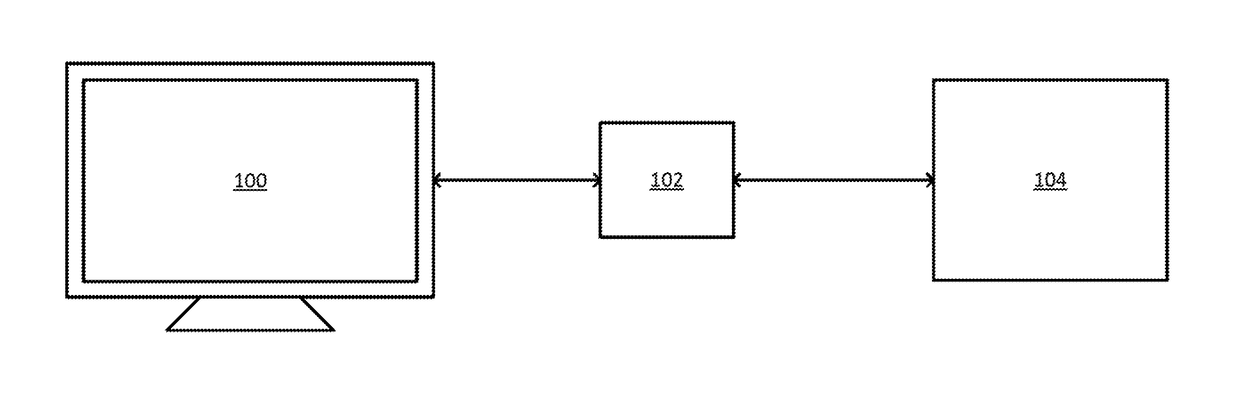
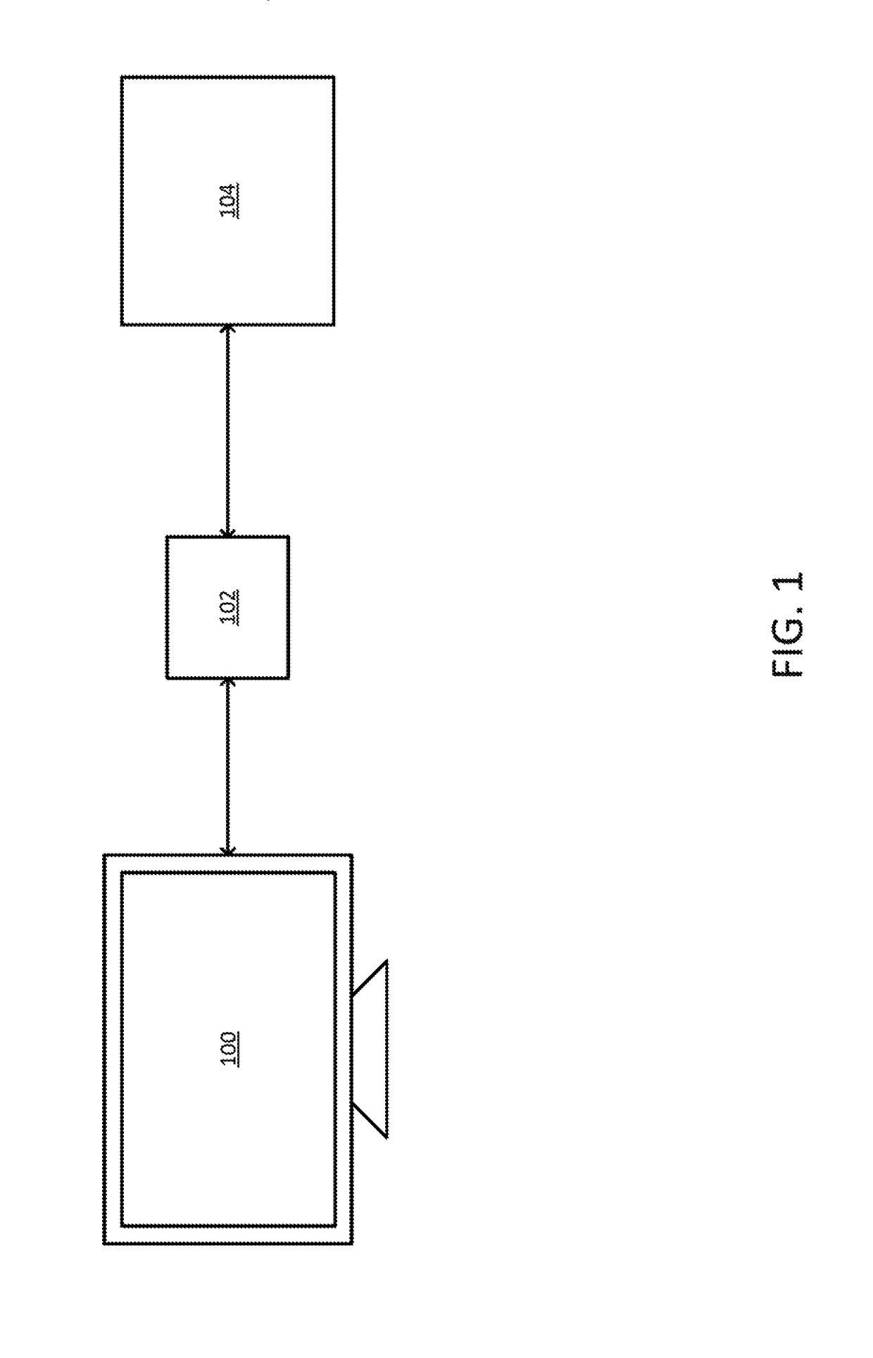
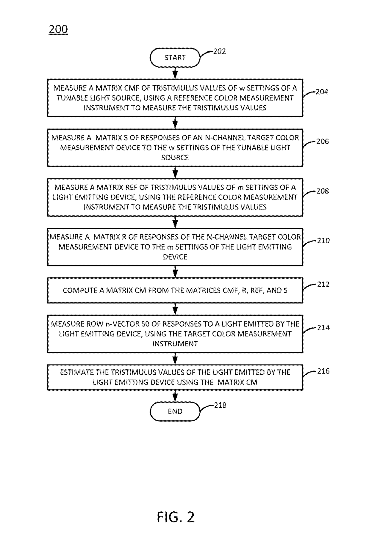
[0012]In one example, the present invention includes a software program for calibrating a multi-channel color measurement instrument so that a difference between the instrument outputs and the color matching functions of the standard observer (according to CIE 1931) is minimized. In one particular example, the present invention includes a software program for calibrating a multi-channel color measurement instrument so that, for a set of lights including lights from a tunable light source (e.g., a monochromator) and test lights from a set of target light sources (e.g., light sources of light emitting devices), a difference between the outputs of the multi-channel color measurement instrument and the XYZ tristimulus values of the standard observer (according to CIE 1931), as measured and computed by a reference spectroradiometer (also referred to herein as a “reference color measurement instrument”), is minimized.

[0013]In one example, the multi-channel color measurement instrument's m...


PUM


Abstract

In one example, an electronic signal is received from a target color measurement instrument that includes a plurality of color channels. A response of the target color measurement instrument to a light emitted by a target light emitting device is extracted from the signal. The response is calibrated to minimize a difference between the response and an output of a color matching function of a standard observer. Calibrating includes multiplying the response by a calibration matrix. The calibration matrix combines measurements of a first plurality of lights from a tunable light source and measurements of a second plurality of lights from the target light emitting device. A first subset of the measurements of the first plurality and second plurality of lights are made by the target color measurement instrument and a second subset of the measurements of the first plurality and second plurality of lights are made by a reference spectroradiometer.

Description

CROSS REFERENCE TO RELATED APPLICATIONS[0001]This application claims the priority of U.S. Provisional Patent Application Ser. No. 62 / 487,169, filed Apr. 19, 2017, which is herein incorporated by reference in its entirety.FIELD OF THE DISCLOSURE[0002]The present invention generally relates to the measurement of color, and more specifically relates to the calibration of color measurement instruments for measuring the color of light emitting objects.BACKGROUND[0003]In order to measure the color of a light emitting object (e.g., a light emitting diode (LED) lamp, a computer monitor, a television, a projector, or the like), a color measuring instrument such as a colorimeter should be able to output color measurement values that correspond to the color matching functions (CMFs) of the standard observer (according to Commission internationale de l'éclairage (CIE 1931)).[0004]It is very difficult, however, to design a color measurement instrument whose three sensors match the CMFs exactly. ...

Claims


Application Information

Patent Timeline
IPC IPC(8): G01N21/25G01J3/52G01J3/02G01J3/46G01J3/51
CPCG01J3/524G01J3/0297G01N21/25G01J3/46G01J3/51G01J3/465G01J3/513G01J3/462
Inventor XU, ZHILINGBRILL, MICHAEL H.
Owner DATACOLOR
Why Eureka
Try Eureka