
Methods and apparatus for providing cloud services to customer premise devices

a technology for premise equipment and cloud services, applied in data switching networks, multiple modulation transmitter/receiver arrangements, selective content distribution, etc., can solve problems such as high nois

Active Publication Date: 2018-04-24
CHARTER COMM OPERATING LLC
View PDF2 Cites 2 Cited by
  • Summary
  • Abstract
  • Description
  • Claims
  • Application Information

AI Technical Summary

Benefits of technology

The patent is about a method for switching between different nodes in a communication network using different modulation levels. The method includes using a high QAM level when the signal to noise ratio is high, to avoid frequent switching. This results in better performance and lower costs for the network.

Problems solved by technology

Empirical test data has shown that the use of lower QAM levels used to provide cloud services allow for higher noise on the communication channel prior to a cloud session being interrupted and / or terminated due to an excessive amount of noise on the communications channel.

Method used


Image

  • Methods and apparatus for providing cloud services to customer premise devices
  • Methods and apparatus for providing cloud services to customer premise devices
  • Methods and apparatus for providing cloud services to customer premise devices

Examples


embodiment 100

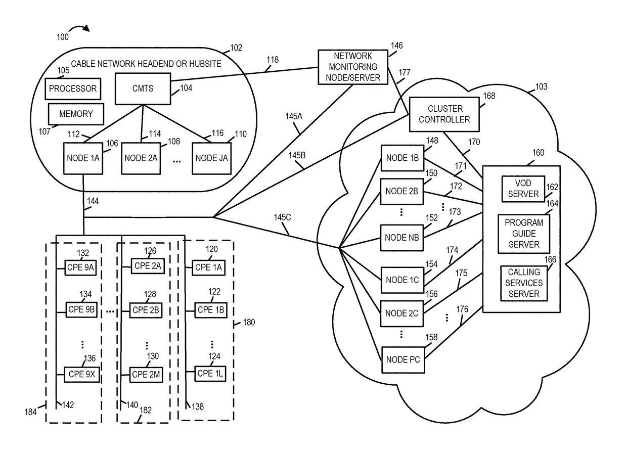
[0044]Exemplary system 100 includes a plurality of customer premises 180, 182, . . . , 184. Each of the customer premises includes one or more customer premise equipment devices coupled to the cloud network 103 and the CMTS 104 via communications links. In the exemplary system embodiment 100, customer premise 180 includes customer premise equipment devices CPE 1A 120, CPE 1B 122, . . . , CPE 1L 124 where L is a positive integer number which are coupled to node 1A 106 via communications links 138 and 144 and via node 1A 106 and communication link 112 to CMTS 104. The customer premise equipment devices CPE 1A 120, CPE 1B 122, . . . , CPE 1L 124 are coupled to networking monitoring node / server / device 146 via communications links 138, 144, and 145A. The customer premise equipment devices CPE 1A 120, CPE 1B 122, . . . , CPE 1L 124 are coupled to cloud cluster controller 168 via communications links 138, 144, and 145B. The customer premise equipment devices CPE 1A 120, CPE 1B 122, . . . ,...

embodiment 600

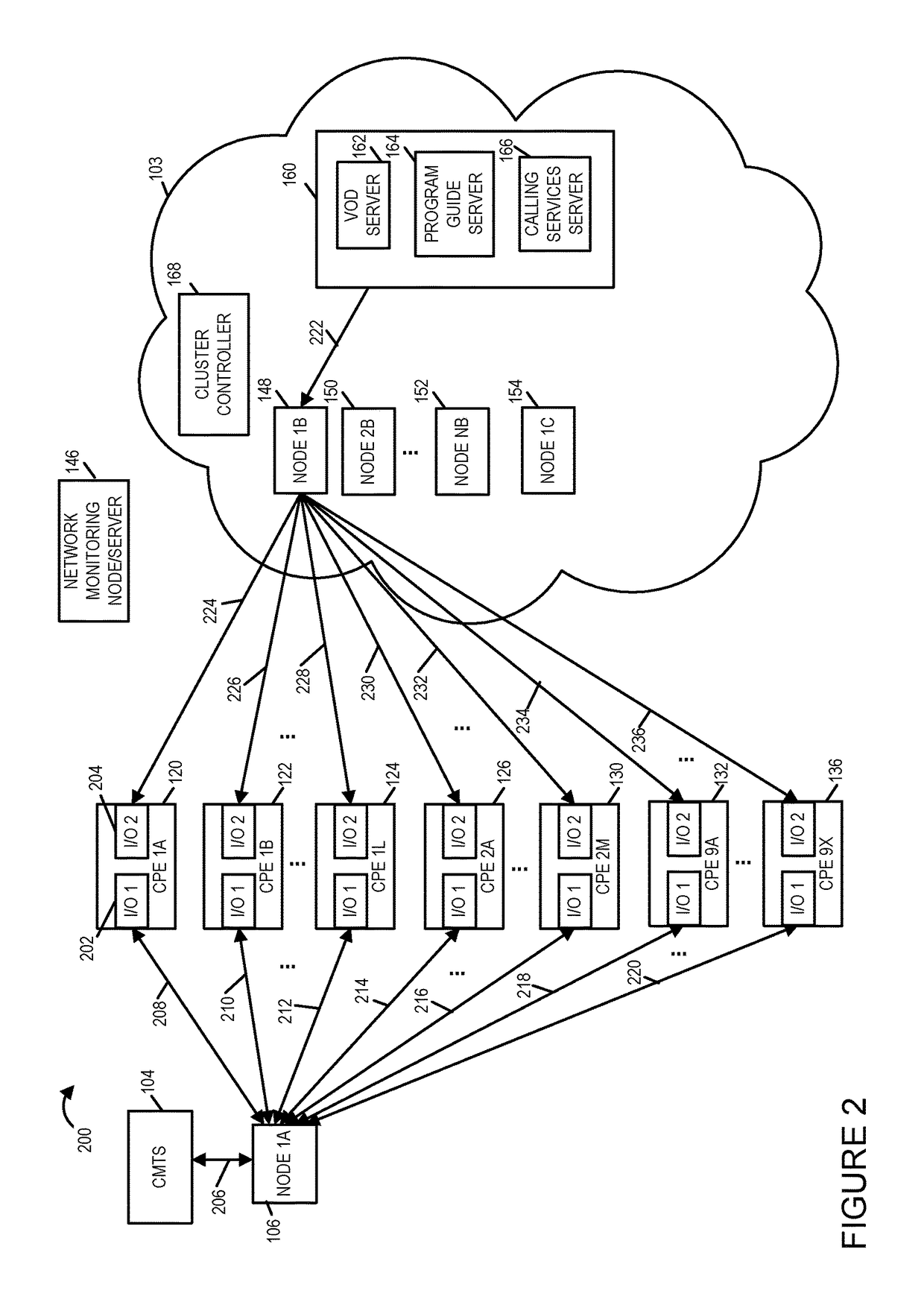
[0063]FIG. 4 illustrates some of the details of an exemplary CPE device 400. CPE device 400 includes a processor 402, e.g., a CPU, an input device 440, e.g. keypad or wireless remote and receiver, an assembly of hardware components 410, e.g., circuits corresponding to different components, a memory 404, an I / O Interface 3424 for interfacing to one or more output devices, e.g., display devices, television sets (TVs), computers, video cassette recorders (VCR), digital video recorders (DVRs), set top boxes (STBs), WIFI devices, routers, and other CPE devices, input / output interfaces, I / O Interface 1412 and I / O Interface 2418, which couple the CPE device to a cable network via link 138 of FIG. 1, and an coupled together via a bus 209 over which the various elements may interchange data and information. internal communication link 430 over which various elements within the CPE device may interchange data, data, and control signals. Memory 404 includes an assembly of software components 4...


PUM


Abstract

Methods and apparatus for adjusting QAM levels used for providing cloud services to customer premise devices on a per customer premise device basis based on determined communication channel signal to noise ratios. One exemplary method embodiment of providing cloud services to a customer premise device (CPE) includes the steps of: determining a signal to noise (SNR), at a first time, on a first communications channel between a network node and the CPE; selecting based on the SNR a cluster node from a plurality of cluster nodes to use to provide a cloud service to the CPE using a second communications channel, at least a first cluster node and a second cluster node in the plurality of cluster nodes using different Quadrature Amplitude Modulation (QAM) levels to communicate with customer premise devices, and using the selected cluster node to provide the cloud service to the CPE.

Description

FIELD OF INVENTION[0001]The present invention relates to methods and apparatus for providing cloud services to customer premise equipment (CPE) devices such as, for example, set-top boxes and in particular for providing cloud services to CPE devices during periods in which the communication / transmission channel over which the cloud services are provided is experiencing less than optimal signal to noise ratios.BACKGROUND OF THE INVENTION[0002]Today, there are a variety of content distribution networks such as cable networks that utilize customer premise equipment (CPE) devices utilizing cloud based services, e.g., programming guide services, digital television programming services, on-demand services including video on-demand (VOD), MPEG video services, gaming services, and internet protocol services, to provide services and content to its customers / subscribers. By using cloud based services, the processing and memory requirements of the CPE devices, e.g., set-top boxes can be reduce...

Claims


Application Information

Patent Timeline
Patent Type & Authority Patents(United States)
IPC IPC(8): H04H60/32H04N21/61H04L27/34H04N21/426H04L29/08H04L12/26H04L12/24H04N21/647H04N21/482H04N21/472H04N21/478
CPCH04N21/64723H04L41/0213H04L43/10H04L67/16H04L27/34H04N21/42676H04N21/6168H04N21/64707H04N21/482H04N21/47202H04N21/478H04L27/0008H04L43/16H04L1/0003H04L1/0015H04L67/51H04L1/0001
Inventor LEVY, DEVIN P.
Owner CHARTER COMM OPERATING LLC
Learn More