High performance linear LED driving circuit

a driving circuit and high-performance technology, applied in the direction of electroluminescent light sources, electric lighting sources, semiconductor lamp usage, etc., can solve the problems of increasing the specification requirement of led, increasing the current or voltage of output current or voltage, and increasing so as to improve the power conversion efficiency of the whole circuit, improve the current constancy of output current, and reduce the requirement of driving voltage

Active Publication Date: 2018-05-08
GIGALINK TECH HLDG LTD
View PDF3 Cites 2 Cited by
  • Summary
  • Abstract
  • Description
  • Claims
  • Application Information

AI Technical Summary

Benefits of technology

[0013]The LED comprises a capacitor of a large capacitance value connected in parallel to the LED to improve the current constancy of the output current to prevent a strobe of the LED.
[0014]In summation, the present invention breaks through the traditional thought and outputs a current with double wave sections in a 180-degree phase sine wave period of the AC voltage, and the duty cycle and current value of the first working section and the second working section vary with a change of the AC voltage, so that the total amount of current of the output current is maintained constant to achieve the effect of a constant output power, so as to improve the power conversion efficiency of the whole circuit and meets the industrial requirements. Therefore, the present invention may be used for 110V LED lamps with 80V or 90V LEDs without requiring the use of the 130V LEDs, and thus greatly lowering the requirement of the driving voltage of the LED, improving the utilization of the LED, and reducing the cost of the lamp.

Problems solved by technology

However, the total output current in a 180-degree phase sine wave period of an AC voltage of an external power supply is non-constant and varies with an increase of the voltage value of the AC voltage, and thus the component specification requirement of the LED becomes higher.
As a result, the output current or voltage will vary and affect the efficiency and THD value of the whole circuit.
As a result, the THD value cannot be maintained stably within the specification, and the product quality will be unstable and unable to launch into some markets.
However, such method incurs complicated circuit architecture and high cost, and it still cannot overcome the problem that the total current of the output current varies with the sinusoidal change of the AC voltage.

Method used


Image

  • High performance linear LED driving circuit
  • High performance linear LED driving circuit
  • High performance linear LED driving circuit

Examples


Embodiment Construction

[0024]The above and other objects, features and advantages of this disclosure will become apparent from the following detailed description taken with the accompanying drawings.

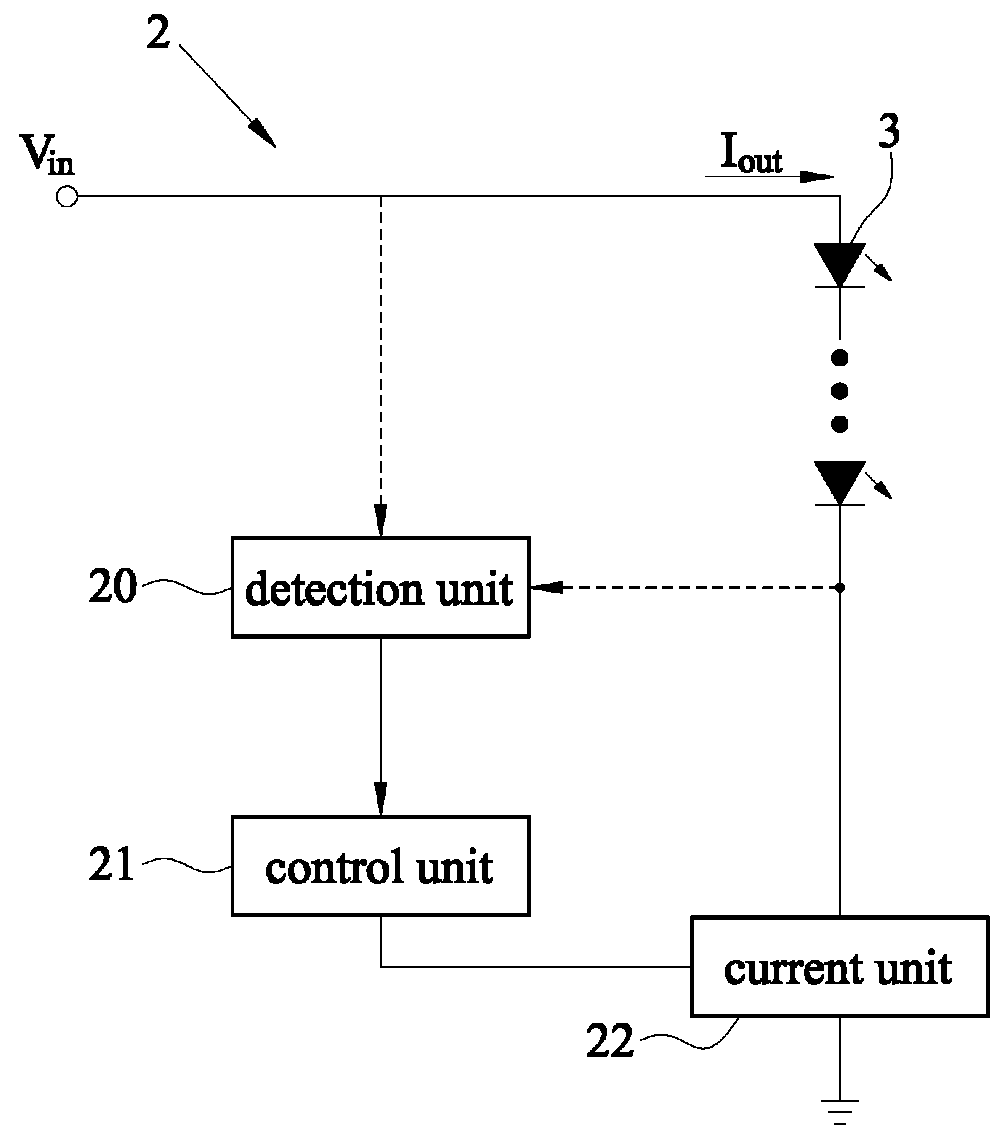
[0025]With reference to FIGS. 3 and 4 for a block diagram and a waveform chart of a high performance linear LED driving circuit 2 in accordance with a preferred embodiment of the present invention respectively, the high performance linear LED driving circuit 2 is provided for converting AC voltage (Vin) of an external power supply into an output current (Lout) of a direct current (DC) and outputting the DC current to at least one LED 3 and comprises a detection unit 20, a control unit 21 and a current unit 22, and the detection unit 20 is electrically coupled to the control unit 21 and the LED 3, and the current unit 22 is electrically coupled to the control unit 21 and the LED 3. In a 180-degree phase sine wave period of the AC voltage, the total current of the output current is formed by a first working sect...


PUM


Abstract

A high performance linear driving circuit converting an AC voltage of an external power supply into a DC output current and then outputs the DC current to at least one LED includes a detection unit, a control unit and a current unit. In a 180-degree phase sine wave period of the AC voltage, the total current of the output current is formed by a first working section, an energy saving section and a second working section, and the detection unit detects at least a voltage value of the AC voltage or a current value of the output current to generate a detection signal, and drives the control unit to modulate the duty cycle and current value of the first working section, energy saving section and second working section, and the amounts of current of the first and second working sections are greater than that of the energy saving section.

Description

FIELD OF THE INVENTION[0001]The present invention generally relates to the field of a light emitting diode (LED) power circuit, particularly to a high performance linear LED driving circuit capable of maintaining a constant total current output through a double-cycle section output current to achieve the effect of high circuit efficiency.BACKGROUND OF THE INVENTION1. Description of the Related Art[0002]After Light Emitting Diode (LED) with the features of low power consumption and high performance hits the lighting market, related manufacturers spare no effort on the subject of controlling the illumination brightness, work efficiency, and service life of LED lamps. Most conventional LED lamps adopt a control circuit with a constant current architecture and connect an LED to an N-Type Metal Oxide Semiconductor Field Effect Transistor (N-MOSFET) and a current resistor in series with, and the current resistor limits the output current passing through the LED. The current resistor recei...

Claims


Application Information

Patent Timeline
Patent Type & Authority Patents(United States)
IPC IPC(8): H05B37/00H05B37/02H05B33/08H05B44/00
CPCH05B33/0812H05B33/0851H05B45/395Y02B20/30
Inventor KUO, CHUN-CHIEHTU, SHIH-PINGYAN, BO-ENHSIAO, CHENG-POHUANG, CHUNG-HSIN
Owner GIGALINK TECH HLDG LTD
Why Eureka
Try Eureka