Eureka AIR delivers breakthrough ideas for toughest innovation challenges, trusted by R&D personnel around the world.

Remote controlled mobile traffic control system and method

a mobile traffic control and remote control technology, applied in the direction of locations, construction, and location information based services, can solve the problems of text-based signage, only being useful in a static work zone, and taking time, so as to reduce the resistance of the mobile platform to movement and improve the ease of towing

Active Publication Date: 2018-05-15
BEAULIEU LEO
View PDF41 Cites 16 Cited by
  • Summary
  • Abstract
  • Description
  • Claims
  • Application Information

AI Technical Summary

Benefits of technology

[0011]It is desired to provide a remote controlled mobile traffic control platform and apparatus which will allow for an operator to remotely control a traffic indication without the need to be directly in harm's way in the oncoming traffic flow.
[0018]The one or more remote control may include a wireless remote control capable of wirelessly positioning the platform as well as changing the indication shown to oncoming traffic, whereby the operator is untethered to the platform and can operate the apparatus from any location within a wireless range of the remote control. In such instance, an operator in a proximate but safe operating position, using the wireless remote control, can move the mobile platform between working locations as required, as well as change the traffic control indication displayed to oncoming traffic. The ability to move the traffic control apparatus within a work zone without the need to disassemble and reassemble it provides a significant efficiency enhancement and safety enhancement over the prior art. While many remote control devices are controlled using a hard wired remote control, the use of a wireless remote control approach further enhances safety in the work zone, insofar as a wired remote control would result in the need to tend and stay clear of a lengthy control cable in the work zone.
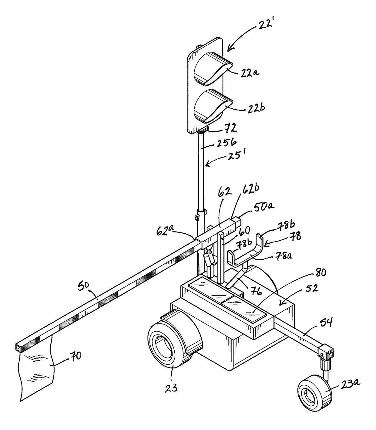
[0037]In one embodiment, the locomotion system comprises a disengagement mechanism operable to decouple one or more driven ground engagement members thereof from one or more motors of the locomotion system to reduce resistance to movement of the mobile platform by means other than said one or more motors of the locomotion system, for example by way of a tow vehicle coupled to the mobile platform by a hitch connector mounted thereon.
[0038]In such instance, there may be a hitch connector carried by the mobile platform for selective coupling thereof to a tow vehicle, whereby decoupling the one or more driven ground engagement members from the one or more motors using the disengagement mechanism provides improved ease of towing.

Problems solved by technology

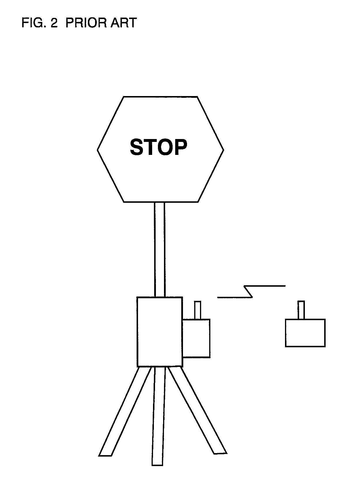
The prior art apparatus of FIG. 2 would only be useful in a static work zone as it cannot easily be moved on the work surface other than by disassembly or movement by human operators.
This would take time, requiring the temporary shutdown of the work zone or implementation of human-performed traffic flagging while the unit is moved.
Potential disadvantages of text-based signage include language barriers, literacy barriers and misinterpretation of the stop message.
The potential downside of such an embodiment relative to the mechanical pendulum-like embodiment of FIGS. 18-20 is the increased electrical power requirement of the electronically controlled self-plumbing action, and potentially greater component cost.
However, due to movement of traffic through the work zone, movement of equipment and work personnel within the work zone, etc., reliable visual sight lines between a camera on the mobile platform and a leader / master unit further down-road in the work zone may not be possible, in which case the GPS approach may prove more useful and reliable.
However, the illuminated state of the other light may cause confusion or distraction to drivers.

Method used


Image

  • Remote controlled mobile traffic control system and method
  • Remote controlled mobile traffic control system and method
  • Remote controlled mobile traffic control system and method

Examples


Embodiment Construction

[0081]Unless defined otherwise, all technical and scientific terms used herein have the same meaning as commonly understood by one of ordinary skill in the art to which the invention belongs. Although any methods and materials similar or equivalent to those described herein can be used in the practice or testing of the present invention, the preferred methods and materials are now described.

[0082]Static Versus Moving Work Zones:

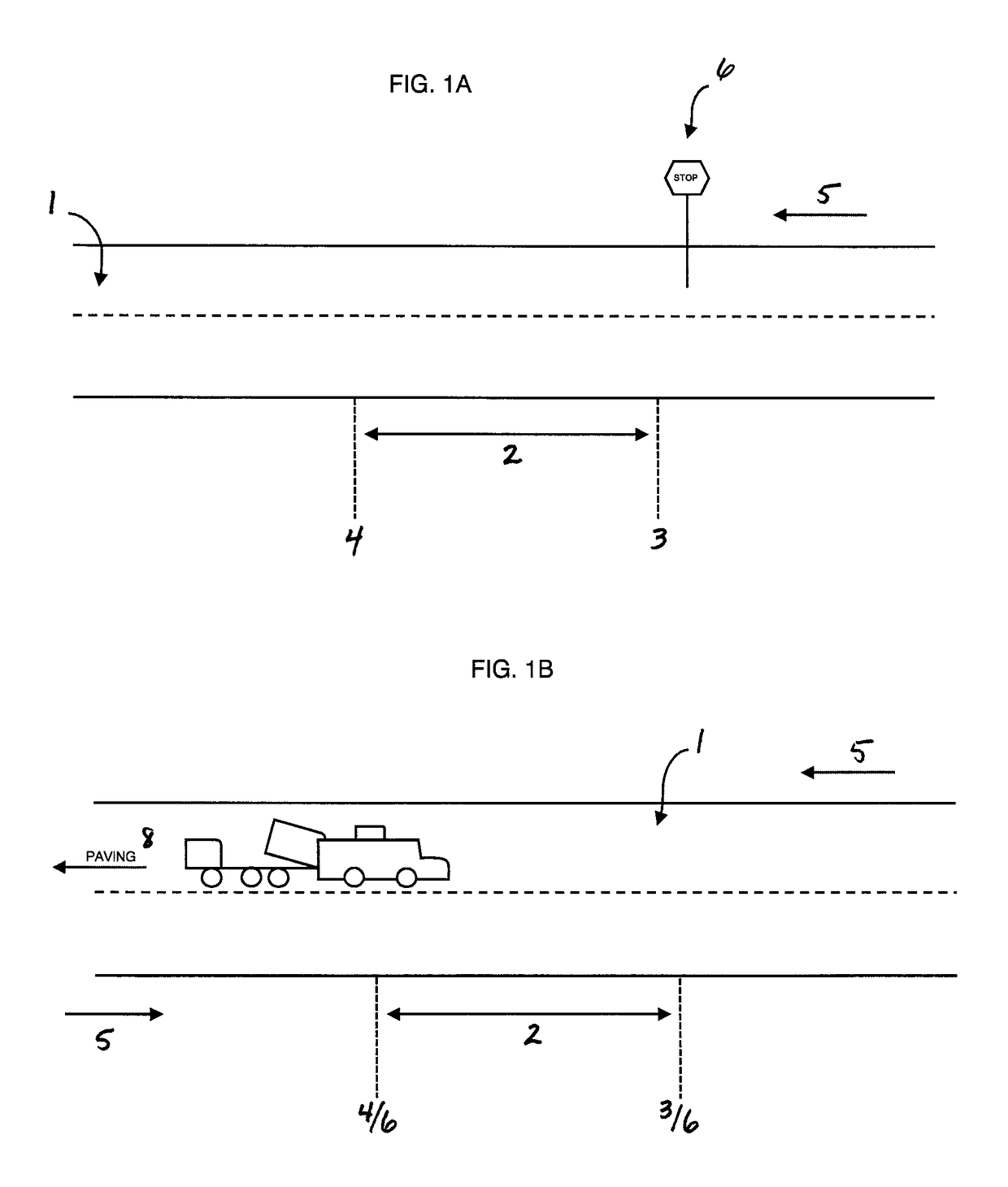
[0083]One problem addressed by the present invention is the need to provide a safer traffic control methodology for use in high danger or moving work zones on vehicular surfaces—the device of the present invention will address the possibility or need for traffic control under remote control in a moving work zone. The concept of a moving versus a static work zone will be understood to those skilled in the art of road construction, maintenance, and other applications such as emergency services and the like requiring a moving work zone. Where the work zone on a ...


PUM


Abstract

A remote controlled mobile traffic control system which can be used in the place of a human flag person. A mobile platform with an adjustable traffic control indicator thereon is controlled by a remote control. The operator can move the platform and change the indication of the traffic control apparatus from a safe distance. The apparatus permits “flagging” of traffic in a moving traffic control zone arrangement, and operational safety is maximized. A traffic barrier arm is movable between deployed and retracted positions obstructing the path of oncoming traffic, for example by a remote controlled actuator or by remote controlled turning of the platform. A remote alarm unit accompanies to the work crew to alarm them of traffic entering the work zone without authorization or at unsafe speed. The apparatus can travel with a moving or changing work zone, either by human remote control or autonomous “follow me” functionality.

Description

FIELD OF THE INVENTION[0001]This invention is in the field of road construction and other traffic control situations including emergency services or the like, and more specifically comprises a remote controlled mobile traffic control apparatus which can be used in the place of a human flag person. The apparatus allows for maximized safety in construction zones and other traffic control areas where there is vehicular traffic, either stationary or mobile in nature.BACKGROUND[0002]There are many industrial applications in which remote control technology can be developed or implemented to maximize efficiency and safety. It is believed that one area in which such technology can be created is that of traffic control in construction or other areas with vehicular traffic.[0003]Traditionally, in construction zones, accident areas or the like, human flag people have been used to provide indications of traffic flow status and the like. In many cases a two sided paddle-like sign is used, provid...

Claims


Application Information

Patent Timeline
Patent Type & Authority Patents(United States)
IPC IPC(8): G08G1/07E01F9/662E01F9/60E01F9/65E01F9/30H04L29/08H04W4/02G08G1/087G08G1/0955
CPCH04L67/18H04W4/02H04W4/023G08G1/07H04L67/00E01F9/60E01F9/65E01F9/662G08G1/087G08G1/0955E01F9/30H04L67/12H04L67/52
Inventor BEAULIEU, LEO
Owner BEAULIEU LEO
Why Eureka
Eureka Blog
Learn More