Placement of wavelength shifters in optical networks

a technology of optical networks and wavelength shifters, applied in data switching networks, wavelength-division multiplex systems, multiplex communication, etc., can solve the problems of greater network resources and less cost-effectiveness

Active Publication Date: 2018-05-15
FUJITSU LTD
View PDF1 Cites 0 Cited by
  • Summary
  • Abstract
  • Description
  • Claims
  • Application Information

AI Technical Summary

Problems solved by technology

Absent direct reachability from the source node to the destination node, an optical signal will be electrically regenerated using optical-electrical-optical (O-E-O) regenerators along a given signal path, which may involve greater network resources and may be less cost effective.
Thus, one challenging goal in optical path computation may be finding an end-end reachable path that includes a minimum or a specified number of regenerators, in addition to satisfying other path constraints, for example, such as a desired level of signal latency or cost.

Method used


Image

  • Placement of wavelength shifters in optical networks
  • Placement of wavelength shifters in optical networks
  • Placement of wavelength shifters in optical networks

Examples


Embodiment Construction

)

[0022]In the following description, details are set forth by way of example to facilitate discussion of the disclosed subject matter. It should be apparent to a person of ordinary skill in the field, however, that the disclosed embodiments are exemplary and not exhaustive of all possible embodiments.

[0023]Throughout this disclosure, a hyphenated form of a reference numeral refers to a specific instance of an element and the un-hyphenated form of the reference numeral refers to the element generically or collectively. Thus, as an example (not shown in the drawings), device “12-1” refers to an instance of a device class, which may be referred to collectively as devices “12” and any one of which may be referred to generically as a device “12”. In the figures and the description, like numerals are intended to represent like elements.

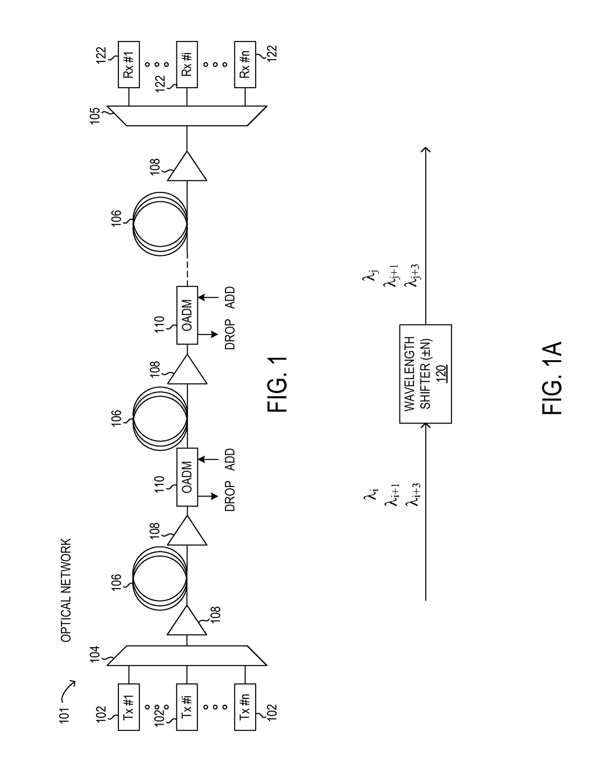
[0024]Referring now to the drawings, FIG. 1 illustrates an example embodiment of optical network 101, which may represent an optical communication system. ...


PUM


Abstract

Methods and systems enable optimized placement of wavelength shifters in optical networks. The wavelength shifters may include O-E-O regenerators for a single wavelength and all optical wavelength shifters for one or more wavelengths. An auxiliary graph is used to represent various links in a provisioned optical path. By applying cost values to each of the links, different types of optimizations for network resource utilization may be realized.

Description

BACKGROUNDField of the Disclosure[0001]The present disclosure relates generally to optical communication networks and, more particularly, to placement of wavelength shifters in optical networks.Description of the Related Art[0002]Telecommunications systems, cable television systems and data communication networks use optical networks to rapidly convey large amounts of information between remote points. In an optical network, information is conveyed in the form of optical signals through optical fibers. Optical networks may also include various network elements, such as amplifiers, dispersion compensators, multiplexer / demultiplexer filters, wavelength selective switches, couplers, etc. configured to perform various operations within the network.[0003]The function of computation of an optical signal path through the various network elements is a core function for design, modeling, management, and control of optical networks. Optical path computation may enable operators of an optical ...

Claims


Application Information

Patent Timeline
Patent Type & Authority Patents(United States)
IPC IPC(8): H04L12/24H04Q11/00H04L12/721H04J14/02
CPCH04L41/0826H04J14/0212H04J14/0217H04J14/0257H04L45/123H04Q11/0066H04L41/145H04Q2011/0079H04Q2011/0047
Inventor KIM, INWOONGWANG, XIPALACHARLA, PAPARAOIKEUCHI, TADASHI
Owner FUJITSU LTD
Why Eureka
Try Eureka