Blade in fan, and fan

a blade and fan technology, applied in the field of blades in fans, can solve the problems of low decreased natural vibration frequency of the platform in a primary vibration mode, and difficulty in ensuring the vibration strength of the platform in a high level, so as to promote the reduction of the weight of the fan, the effect of reducing the weight of the blade and reducing the rigidity of the platform

Active Publication Date: 2018-05-22
IHI CORP
View PDF18 Cites 0 Cited by
  • Summary
  • Abstract
  • Description
  • Claims
  • Application Information

AI Technical Summary

Benefits of technology

[0007]A diameter of the fan tends to be larger by request for a higher bypass ratio for the purpose of improvement in fuel consumption of the aircraft engine, and along with that, not only a length in the radial direction of the fan outlet guide blade, but an axial length (a length in the axial direction) of the fan outlet guide blade extend. Therefore, rigidity of the platform becomes low, a natural vibration frequency of the platform in a primary vibration mode decreases, and it becomes difficult to secure vibration strength of the platform in a high level. Meanwhile, although it is also considered that ribs for reinforcing the platform are continuously formed on the opposite surface (an inner surface in the radial direction) of the flow passage surface of the platform from the upstream end side to the downstream end side of the platform via an axial center of the platform to thereby enhance the rigidity of the platform, weight of the outlet guide blade increases, and thus reduction in weight of the fan, i.e., reduction in weight of the aircraft engine becomes difficult.
[0009]Consequently, an object of the present disclosure is to provide a fan in an aircraft engine and a blade used in the fan that can solve the above-mentioned problem.
[0013]According to the present disclosure, since a natural vibration frequency of the platform in a primary vibration mode can be more sufficiently increased than a case where the ribs are continuously formed from the upstream end side to the downstream end side of the platform via the axial center of the platform, vibration strength of the platform can be secured in a high level, while reducing weight of the blade in the fan to thereby promote reduction in weight of the fan, i.e., reduction in weight of the aircraft engine.

Problems solved by technology

Therefore, rigidity of the platform becomes low, a natural vibration frequency of the platform in a primary vibration mode decreases, and it becomes difficult to secure vibration strength of the platform in a high level.
Meanwhile, although it is also considered that ribs for reinforcing the platform are continuously formed on the opposite surface (an inner surface in the radial direction) of the flow passage surface of the platform from the upstream end side to the downstream end side of the platform via an axial center of the platform to thereby enhance the rigidity of the platform, weight of the outlet guide blade increases, and thus reduction in weight of the fan, i.e., reduction in weight of the aircraft engine becomes difficult.
That is, there is a problem that it is difficult to secure the vibration strength of the platform in the high level, while promoting the reduction in weight of the aircraft engine.

Method used


Image

  • Blade in fan, and fan
  • Blade in fan, and fan
  • Blade in fan, and fan

Examples


Embodiment Construction

[0019]The present disclosure is based on the following knowledge obtained by the inventor of the present application.

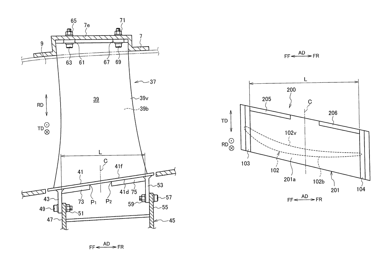
[0020]FIG. 4A is a view showing an opposite surface 101a side of a flow passage surface of a platform 101 of a fan outlet guide blade 100 according to a comparative example. FIG. 4B is a view showing an opposite surface 201a side of a flow passage surface of a platform 201 of a fan outlet guide blade 200 according to an example of the present disclosure. FIG. 5A is a view showing a flow passage surface 301a side of a platform 301 of a fan outlet guide blade 300 as an analysis object. FIG. 5B is a view showing a result (i.e., a primary vibration mode shape) of primary vibration mode analysis of displacement of the platform 301 during operation of an aircraft engine. Note that a same symbol is attached to a same member in these drawings. As shown in FIG. 4A, the fan outlet guide blade 100 according to the comparative example includes a rib 105 in at least either of a po...


PUM


Abstract

A platform of a fan outlet guide blade has a first rib and a second rib in an opposite surface of a flow passage surface thereof. The first rib and the second rib are formed in portions excluding a predetermined area separated to an upstream side and a downstream side by 8 to 30% of an inter-flange distance between a first flange and a second flange with respect to an axial center of the platform, the portions being located on a pressure surface side in the opposite surface.

Description

CROSS REFERENCE TO RELATED APPLICATIONS[0001]This application is a continuation application of International Application No. PCT / JP2014 / 064574, filed on Jun. 2, 2014, which claims priority to Japanese Patent Application No. 2013-119562, filed on Jun. 6, 2013, the entire contents of which are incorporated by references herein.BACKGROUND[0002]1. Field[0003]The present disclosure relates to a fan in an aircraft engine, and a blade used in the fan, such as a fan outlet guide blade.[0004]2. Description of the Related Art[0005]In recent years, various developments of a fan outlet guide blade (a fan stator vane), which is a component of a fan, have been performed (refer to Japanese Patent Laid-Open Publication Nos. 2011-196179 and 2008-82337).[0006]The fan outlet guide blade includes a guide blade body as a blade body. The guide blade body has a pressure surface (a positive pressure surface) on one side in a blade thickness direction, and has a suction surface (a negative pressure surface)...

Claims


Application Information

Patent Timeline
Patent Type & Authority Patents(United States)
IPC IPC(8): F01D5/14F01D9/04F04D29/54F01D9/02F04D29/64F01D17/10F01D25/24F01D25/16F02C7/20
CPCF01D9/02F01D9/041F01D17/105F01D25/162F01D25/24F01D25/246F04D29/541F04D29/542F04D29/644F02C7/20Y02T50/671F05D2220/323F05D2240/12F05D2240/80Y02T50/60
Inventor OGAWARA, KAZUTO
Owner IHI CORP
Why Eureka
Try Eureka