
Method and apparatus for identifying the winding short of bar wound electric machine at standstill condition

a technology of winding shorts and electric machines, which is applied in the direction of dynamo-electric machine testing, measurement devices, instruments, etc., can solve the problems of motor damage or failure, deterioration and breakdown of insulation, etc., and achieve the effect of avoiding inductance variation and preventing the possibility of motor damag

Active Publication Date: 2018-05-29
GM GLOBAL TECH OPERATIONS LLC
View PDF7 Cites 3 Cited by
  • Summary
  • Abstract
  • Description
  • Claims
  • Application Information

AI Technical Summary

Benefits of technology

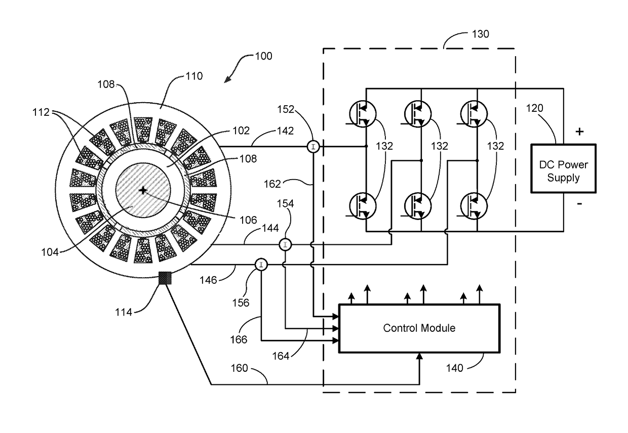
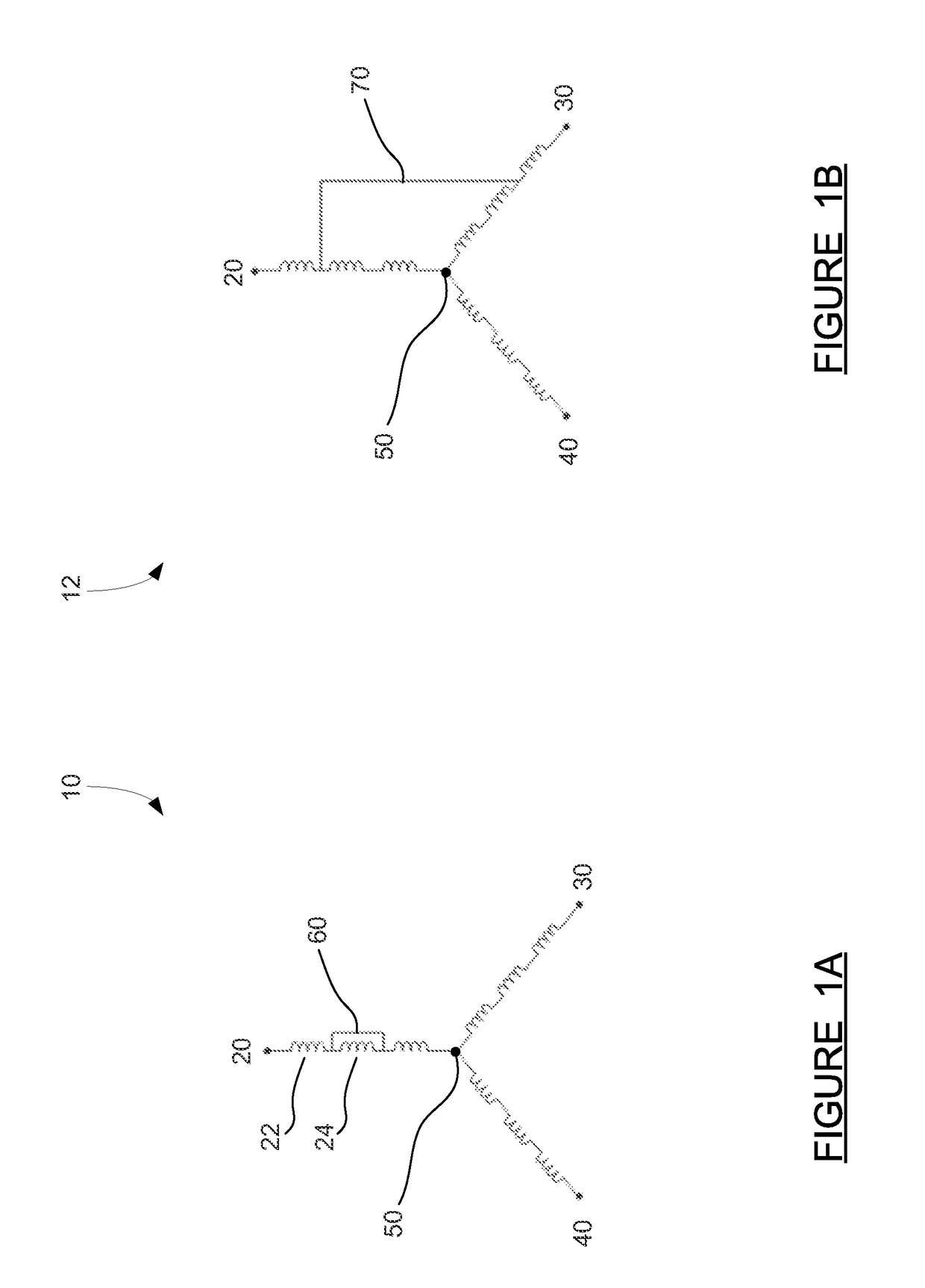
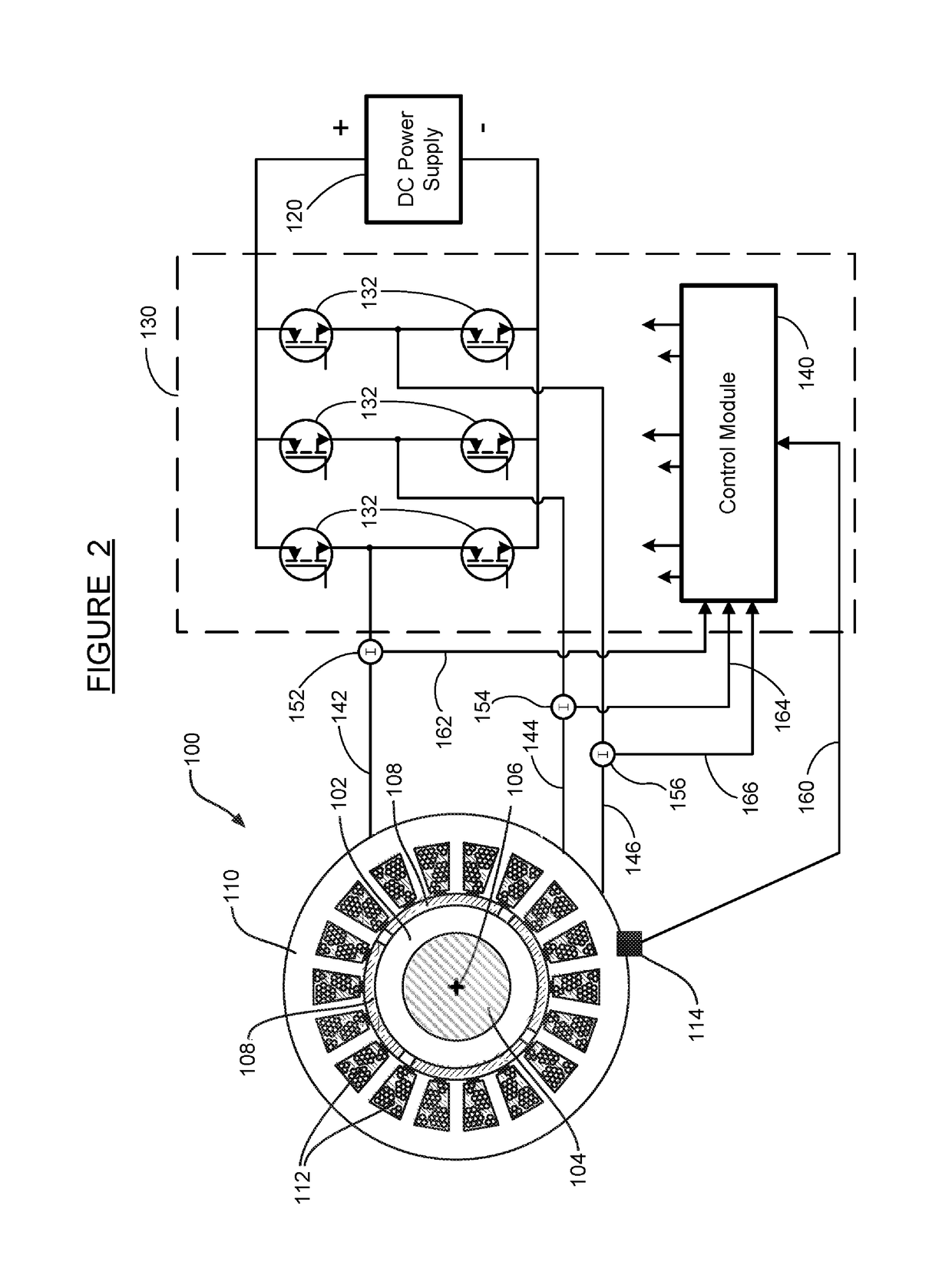
[0011]In accordance with the teachings of the present invention, a method and system are disclosed for detecting turn-to-turn and phase-to-phase winding short circuits in an electric motor. The motor is tested at a standstill condition by injecting a current signal into the virtual d-axis of the motor while controlling q-axis current to zero. Steady state feedback current from the motor is measured, and current harmonics are calculated using FFT or peak-to-peak techniques. It is determined that a short circuit is present in the winding if feedback current harmonics above a nominal level are detected, where the increased feedback current is an indication that winding inductance has decreased due to a short circuit. Testing at standstill using a small current advantageously prevents the possibility of damaging the motor and avoids inductance variation due to changing rotor position.

Problems solved by technology

The rotor winding is subjected to a variety of loads, stresses and environmental factors—including centrifugal forces, thermal expansion / contraction, vibration, high voltages and high temperatures—which can lead to deterioration and breakdown of the insulation.
Winding short circuit faults, if present during operation, can cause motor damage or failure.

Method used


Image

  • Method and apparatus for identifying the winding short of bar wound electric machine at standstill condition
  • Method and apparatus for identifying the winding short of bar wound electric machine at standstill condition
  • Method and apparatus for identifying the winding short of bar wound electric machine at standstill condition

Examples


Embodiment Construction

[0016]The following discussion of the embodiments of the invention directed to a method and apparatus for diagnosing a stator winding short circuit by detecting an inductance reduction in the winding is merely exemplary in nature, and is in no way intended to limit the invention or its applications or uses.

[0017]Electric motors are used for many applications, and have become an indispensable part of modern life. One increasingly common use of electric motors is to provide propulsion in electric vehicles and hybrid-electric vehicles. In such vehicles, a high-capacity battery pack stores electrical energy—which may come from a plug-in charge, or an onboard engine / generator, or both—and the battery pack provides the electrical energy to the motor to drive the vehicle. Although the battery pack itself can provide only direct current (DC), an inverter may be used to provide alternating current (AC) to the motor, which may be a three-phase permanent magnet (PM) motor, for example. Regardl...


PUM


Abstract

A method and system are disclosed for detecting turn-to-turn and phase-to-phase winding short circuits in an electric motor. The motor is tested at a standstill condition by injecting a current signal into the virtual d-axis of the motor while controlling q-axis current to zero. Steady state feedback current from the motor is measured, and current harmonics are calculated using FFT or peak-to-peak techniques. It is determined that a short circuit is present in the winding if feedback current harmonics higher than a nominal level are detected, where the increased feedback current is an indication that winding inductance has decreased due to a short circuit. Testing at standstill using a small current advantageously prevents the possibility of damaging the motor and avoids inductance variation due to changing rotor position.

Description

BACKGROUND OF THE INVENTION[0001]Field of the Invention[0002]This invention relates generally to short circuit detection in electric machines and, more particularly, to a technique for identifying turn-to-turn and phase-to-phase winding shorts in an electric motor at standstill by injecting a current signal into the virtual d-axis of the motor while controlling q-axis current to zero, measuring feedback current from the motor, and determining that a short circuit is present in the winding if winding inductance has decreased as indicated by increased feedback current harmonics.[0003]Discussion of the Related Art[0004]Known electric motors include permanent magnet electric motors and other induction motors that transform electric power to mechanical torque. Permanent magnet electric motors may be multiphase permanent magnet (PM) electric motors that include permanent magnets as part of a rotor core and aligned longitudinally with an axis of rotation. Known stators include an annular s...

Claims


Application Information

Patent Timeline
Patent Type & Authority Patents(United States)
IPC IPC(8): G01R31/02G01R31/06G01R31/34
CPCG01R31/346G01R31/06
Inventor HAO, LEILOPEZ-MARTINEZ, CRISTIAN A.FREITAS, CHAD A.
Owner GM GLOBAL TECH OPERATIONS LLC
Learn More