
3D imaging method and system

a three-dimensional imaging and system technology, applied in the field of three-dimensional imaging, can solve the problems of difficult analysis of static two-dimensional thermal infrared images by medical practitioners, lack of information on inability of medical practitioners to obtain the information of the location and orientation of objects, etc., to achieve the effect of convenient commercial choi

Active Publication Date: 2018-05-29
COMMONWEALTH SCI & IND RES ORG
View PDF5 Cites 8 Cited by
  • Summary
  • Abstract
  • Description
  • Claims
  • Application Information

AI Technical Summary

Benefits of technology

The invention seeks to improve upon the prior art by providing consumers with better features and benefits. It also aims to overcome or alleviate the shortcomings of the prior art and offer a useful commercial option.

Problems solved by technology

Energy sustainability is a major challenge of the 21st century in the face of climate change.
A problem with such energy auditing systems of the prior art is that they lack information on the location and orientation of objects with reference to each other, particularly across separate images.
A further problem with such energy auditing systems of the prior art is that the thermal infrared imaging indirectly measures a temperature of an object by capturing thermal infrared radiation from a surface of the object.
A problem with medical thermal infrared imaging of the prior art is that imaging artefacts are often present on edges of objects, objects far from the sensor, or areas where an angle of incidence is great.
Similarly, it is often difficult for a medical practitioner to analyse a static two-dimensional thermal infrared image and compare thermal infrared images taken at different times, distances and angles
One problem with such systems is that they are costly, as several thermal infrared sensors are required.
A further problem with such systems is that they are unable to map arbitrarily sized structures.
Yet a further problem of prior art medical thermal infrared imaging systems is that they may need to be repositioned and recalibrated at several locations around the patient in order to take multiple views.
Calibration of these systems is also complex and generally requires the expertise of a trained engineer.
A general problem with thermal infrared imaging of the prior art is that the thermal infrared image data often varies depending on an angle and distance between the object and the camera during capture.

Method used


Image

  • 3D imaging method and system
  • 3D imaging method and system
  • 3D imaging method and system

Examples


Embodiment Construction

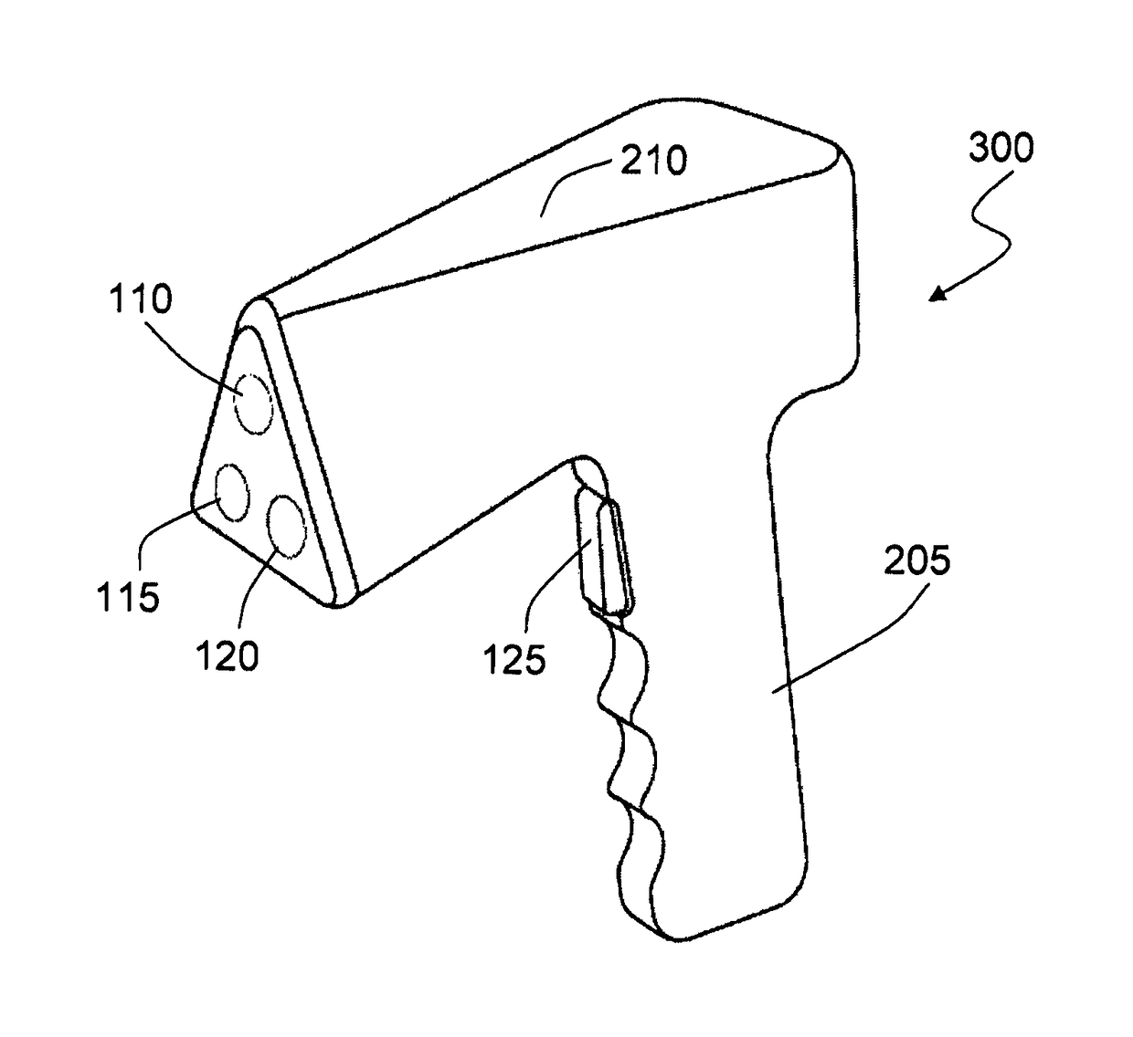
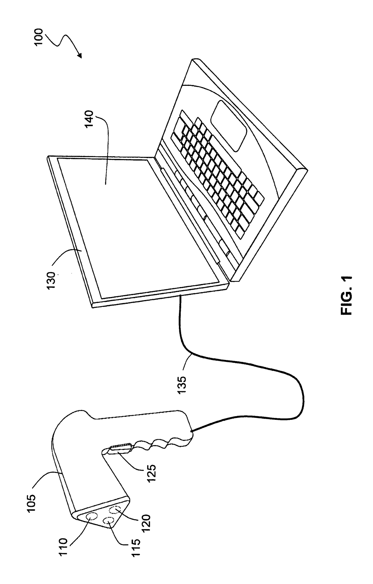
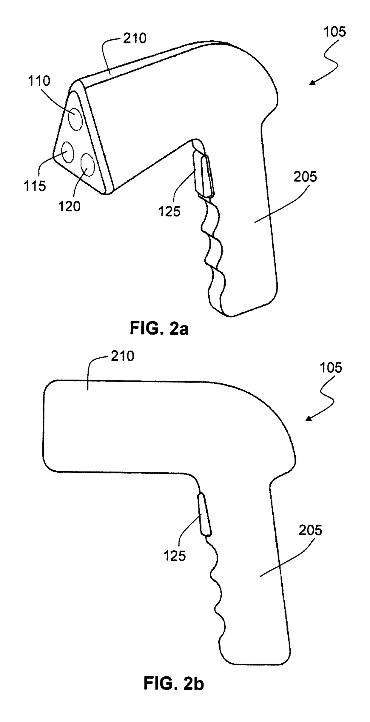
[0115]Embodiments of the present invention comprise three-dimensional imaging devices and methods. Elements of the invention are illustrated in concise outline form in the drawings, showing only those specific details that are necessary to the understanding of the embodiments of the present invention, but so as not to clutter the disclosure with excessive detail that will be obvious to those of ordinary skill in the art in light of the present description.

[0116]In this patent specification, adjectives such as first and second, left and right, front and back, top and bottom, etc., are used solely to define one element or method step from another element or method step without necessarily requiring a specific relative position or sequence that is described by the adjectives. Words such as “comprises” or “includes” are not used to define an exclusive set of elements or method steps. Rather, such words merely define a minimum set of elements or method steps included in a particular embo...


PUM


Abstract

A system for generating a three-dimensional model of an object, the system including a portable hand-held imaging device including a housing, a plurality of sensors attached to the housing and at least one electronic processing device coupled to the plurality of sensors. The electronic processing device determines from the plurality of sensors, while the imaging device is in at least two different poses relative to the object, range data indicative of a range of the object and thermal infrared data indicative of a thermal infrared image of the object, generates a three-dimensional model based at least partially upon the range data from the at least two different poses and associates model data derived from the thermal infrared data from the at least two different poses with the three dimensional model to thereby provide a three dimensional thermal infrared model of the object.

Description

CROSS REFERENCE TO RELATED APPLICATIONS[0001]This application is a U.S. National Phase Application under 35 U.S.C. 371 of International Application No. PCT / AU2014 / 000174 filed on Feb. 25, 2014 and published as WO 2014 / 127431 A1 on Aug. 28, 2014. This application is based on and claims the benefit of priority from Australian Application No. 2013900667 filed on Feb. 25, 2013. The entire disclosures of all of the above applications are incorporated herein by reference.FIELD OF THE INVENTION[0002]The present invention relates to three-dimensional imaging. In particular, although not exclusively, the invention relates to a system and method for three-dimensional imaging utilising thermal infrared image data.BACKGROUND TO THE INVENTION[0003]The reference in this specification to any prior publication (or information derived from it), or to any matter which is known, is not, and should not be taken as an acknowledgment or admission or any form of suggestion that the prior publication (or i...

Claims


Application Information

Patent Timeline
Patent Type & Authority Patents(United States)
IPC IPC(8): H04N5/33G03B35/02G06T17/00G06T15/06G06T11/00G06T7/593G06T7/90G06T15/04
CPCH04N13/25H04N5/33G03B35/02G06T7/593G06T7/90G06T15/04G06T15/06G06T17/00G06T11/008G06T2207/10048G06T2207/10012G06T2207/10028H04N23/23
Inventor MOGHADAM, PEYMAN
Owner COMMONWEALTH SCI & IND RES ORG
Learn More