Reduced glare LED light device

a led light and reduced glare technology, applied in semiconductor devices, lighting and heating equipment, instruments, etc., can solve the problems of increasing glare, lack of seamless transitional light source, and inability to provide seamless and transitional light source, so as to reduce glare, improve lighting safety, and full optical control of light

Inactive Publication Date: 2018-06-05
DEDICK CORY D
View PDF1 Cites 3 Cited by
  • Summary
  • Abstract
  • Description
  • Claims
  • Application Information

AI Technical Summary

Benefits of technology

[0017]An advantage of the invention is that it provides significant reduction in glare for LED lighting while maintaining full optical control of the light. This approach is departs from previous optical systems that are designed for maximum output of light.
[0018]Another advantage of the invention is that it provides improved safety from lighting. By reducing the glare factor with LED street lights, drivers will be able to not only see better on the roadway, they wont be plagued by temporary night blindness due to glare flash in their eyes.
[0019]A further advantage of the invention is that it provides an LED in which the overall effect of blending the light will be a reduction in the spotty look of individual diodes and allows for a much more pleasing and unified look from the light source.

Problems solved by technology

As LED technology has advanced and the diodes have gotten brighter there has been an increasing glare issue due to the intensity of the light source.
This glare is increasingly a safety hazard for motorists driving at night.
While seemingly effective, this approach lacks the ability to provide a seamless and transitional light source.
The resulting array becomes spotty and often incorporates the use of a more complex plate system with openings for each optic.
This extensively complicates the assembly process with many parts that are more expensive and labor intensive while still not pleasing to the eye in its final result.
The approach can be somewhat effective in solving the glare issue, but there is a definite loss of light due to bouncing it off of a reflective surface and there is a loss of beam control as well.
This approach also makes for a more bulky fixture and can be a poor utilization of leveraging the flexible strengths of implementation LED technology.

Method used


Image

  • Reduced glare LED light device
  • Reduced glare LED light device
  • Reduced glare LED light device

Examples


Embodiment Construction

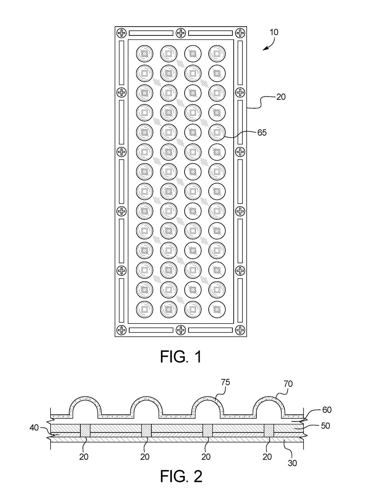
[0026]FIG. 1 illustrates an example of a light device 10. As shown in FIG. 1, the light device 10 may be embodied as a planar light source including an array of LED lights. The light device 10 may be adapted to provide light from nearly its entire surface area by spreading out the light from LED lights embedded within. The dispersal of the light energy minimizes angular refraction and significantly decreases the glare emitted by each individual diode in the light device 10.

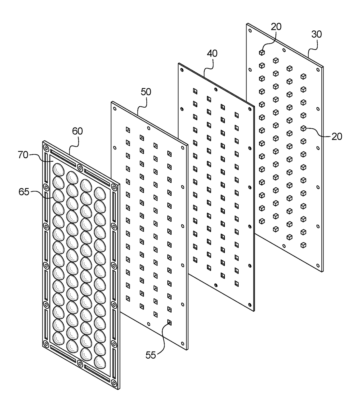
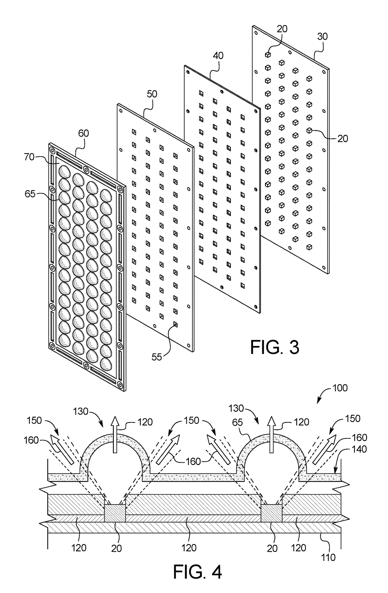
[0027]FIG. 2 illustrates a cross section of the light device 10. The relative thickness of the elements shown in FIG. 2 is exaggerated for the purposes of illustration. Likewise, FIG. 3 illustrates an exploded perspective view of the light device 10.

[0028]In one example, the light device 10 includes a layer of LED lights 20. The LED lights 20 may be an array of diodes mounted on a circuit board 30. A layer of highly reflective film 40, such as Mylar® brand film, may be placed over the circuit board, with the LED l...


PUM

PropertyMeasurementUnit
translucentaaaaaaaaaa
thicknessaaaaaaaaaa
flexible strengthsaaaaaaaaaa

Abstract

A device for providing light including: a housing; an array of a plurality of LED lights mounted to the housing, wherein, when active, each LED emits a highest intensity beam of light along a primary axis and emits a lower intensity beam of light along a secondary axis; a lens mounted to the housing, the lens including an optic element corresponding to each of the plurality of LED lights, each optic element intersected by the primary axis of the corresponding LED light; and a translucent edge-light diffusing layer located between two or more of the plurality of LED lights, the edge diffusing layer is not intersected by the primary axis and is intersected by the secondary axis of the LED lights.

Description

CROSS-REFERENCE TO RELATED APPLICATIONS[0001]This application incorporates by reference and claims the benefit of priority to U.S. Provisional Patent Application No. 62 / 155,277 filed Apr. 30, 2015.BACKGROUND OF THE INVENTION[0002]The present subject matter relates generally to a device that provides light with reduced glare using light emitting diodes. More specifically, the present invention relates to an LED light source that filters and spreads light from the LEDs using various optical components before emitting the light in a target direction.[0003]As LED technology has advanced and the diodes have gotten brighter there has been an increasing glare issue due to the intensity of the light source. This glare is increasingly a safety hazard for motorists driving at night.[0004]Previous LED light systems have tried using angular refraction to reduce glare, while others have tried to use more conventional means of putting the LED diodes into a reflector housing and not using individu...

Claims


Application Information

Patent Timeline
Patent Type & Authority Patents(United States)
IPC IPC(8): F21V3/00F21V13/12F21V8/00F21V5/00F21V3/04F21V7/05F21K9/66F21K9/69F21Y105/16F21Y115/10
CPCF21V3/0625F21V5/007G02B6/0035F21V3/12F21K9/66F21V3/049F21V7/05F21Y2105/16F21Y2115/10F21K9/69F21V13/12
Inventor DEDICK, CORY D
Owner DEDICK CORY D
Why Eureka
Try Eureka