Aperture-fold imaging system

a technology of optical systems and apertures, applied in the field of aperture-folded optical systems, can solve the problems of obstructing a portion of the optical path, revealing unobstructed folded optical systems, and relatively large telescopes

Active Publication Date: 2018-06-05
CHARLES STARK DRAPER LABORATORY
View PDF3 Cites 0 Cited by
  • Summary
  • Abstract
  • Description
  • Claims
  • Application Information

AI Technical Summary

Benefits of technology

[0018]The first surface may be coated with a metamaterial configured to prevent substantially any light passing through the first surface from outside the optical block into the optical path.

Problems solved by technology

Some folded optical systems, such as early Newtonian telescopes, dispose one or more of the reflecting elements within an optical path, thereby obstructing a portion of the optical path.
Judicial placement of reflecting optical elements can, however, yield unobstructed folded optical systems.
However, such telescopes are relatively physically large.

Method used


Image

  • Aperture-fold imaging system
  • Aperture-fold imaging system
  • Aperture-fold imaging system

Examples


Embodiment Construction

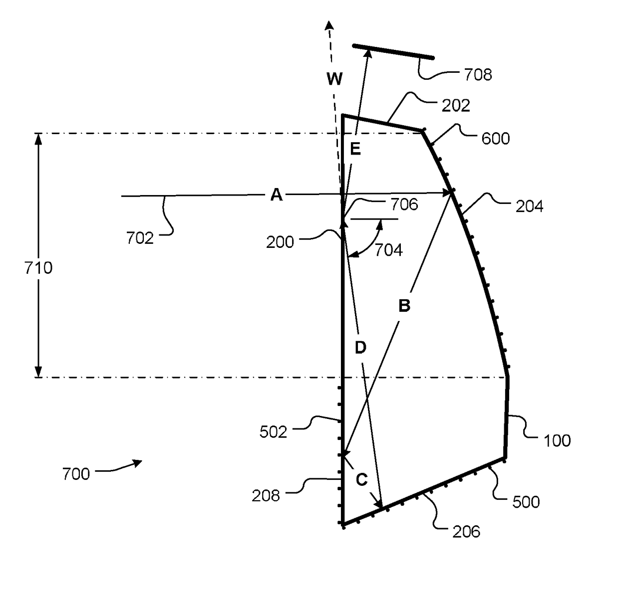
[0005]An embodiment of the present provides an optical system. The optical system includes an optical block. The optical block defines an aperture. The aperture is configured to admit an optical signal along an optical path into the optical block.

[0006]The optical block also defines a first surface. The first surface is opposite the aperture, along the optical path. The first surface is configured to allow the optical signal to impinge on the first surface after being admitted by the aperture. The first surface is also configured to allow the optical signal to impinge on the first surface before being reflected by any other surface of the optical block. The first surface is also configured to prevent substantially any light passing through the first surface from outside the optical block into the optical path.

[0007]The optical block also defines a first mirror. The first mirror is disposed along the optical path. The first mirror is configured to fold the optical path at the first m...


PUM


Abstract

A folded optical system includes a powered optical element, at least one folding mirror and an aperture and defines an optical path through the optical system. The powered optical element, the at least one folding mirror and the aperture are configured to fold the optical path at the aperture, thereby providing a compact optical system. The optical system may include an optical block that totally internally reflects the optical signal at the aperture. Optionally or alternatively, discrete optical components may be used, such as an aperture made of a conventional material or a metamaterial, an off-axis parabolic mirror or lens and one or more folding mirrors. Some embodiments include a wavelength dispersive element, so as to implement a spectrometer.

Description

CROSS REFERENCE TO RELATED APPLICATIONS[0001]This application is a divisional of U.S. patent application Ser. No. 14 / 308,276, filed Jun. 18, 2014, titled “Aperture-Fold Imaging System,” which claims the benefit of U.S. Provisional Patent Application No. 61 / 842,634, filed Jul. 3, 2013, titled “Aperture-Fold Imaging System,” the entire contents of each of which are hereby incorporated by reference herein, for all purposes.TECHNICAL FIELD[0002]The present invention relates to folded optical systems and, more particularly, to a folded optical system in which at least one fold occurs at an aperture of the system.BACKGROUND ART[0003]Optical systems, such as telescopes, often require optical paths of specific lengths, such as focal lengths of optical elements. To reduce physical size of an optical system, an optical path may be folded one or more times by one or more reflecting elements, typically mirrors. Some folded optical systems, such as early Newtonian telescopes, dispose one or more...

Claims


Application Information

Patent Timeline
Patent Type & Authority Patents(United States)
IPC IPC(8): G02B5/08G02B17/08G02B17/02G02B27/00G02B23/06G02B27/42
CPCG02B17/023G02B27/0025G02B23/06G02B17/086G02B27/4205G02B17/0832G02B17/08
Inventor LAINE, JUHA-PEKKA J.ROGOMENTICH, FRANCIS J.SMITH, STEPHEN P.LARSEN, ROBERT
Owner CHARLES STARK DRAPER LABORATORY
Why Eureka
Try Eureka