Device for preparing a solution, in particular in or on a dialysis machine

a dialysis machine and device technology, applied in the field of devices for preparing solutions, can solve the problems of low cost, inability to use the mentioned connector system of bags, lack of dimensional stability, etc., and achieve the effect of low cos

Active Publication Date: 2018-06-12
B BRAUN AVITUM
View PDF21 Cites 0 Cited by
  • Summary
  • Abstract
  • Description
  • Claims
  • Application Information

AI Technical Summary

Benefits of technology

[0007]Thus, an object on the basis of the invention is to provide a receptacle which can be used in currently common extracorporeal blood treatment machines such as dialysis machines comprising cartridge connection systems, which eliminates the disadvantages of prior art and can also be produced at low costs.
[0026]Among others, the device according to aspects of the invention has the following advantages:
[0027]Due to the fact that the supporting element is surrounded by the container medium in a protective and shock-absorbing manner and the container itself is flexible, the device is extremely break-proof (“not prone to breaking”), so that an increased transport safety is achieved. Due to the flexibility of the container (which does not have to absorb any clamping forces), the device is also vacuum-proof. The device can be produced at low cost. In addition, the device can be connected to common dialysis machines, as the inner supporting element undertakes, among others, the function of the sturdy container wall which is known from prior art.

Problems solved by technology

Bag-shaped receptacles cannot be used in the mentioned connector system due to their lack of dimensional stability.
The firm PP injection-molded cartridges are very fragile and often show transport damages.
In addition, rigid cartridges tend to implode if their interior is below atmospheric pressure.
With bag-shaped receptacles, however, as they are used in medical science for other purposes (such as for infusion purposes), there is no possibility to connect them to the dialysis machines of the type mentioned above, and complex feed and discharge lines along with sieve elements are required.

Method used


Image

  • Device for preparing a solution, in particular in or on a dialysis machine
  • Device for preparing a solution, in particular in or on a dialysis machine
  • Device for preparing a solution, in particular in or on a dialysis machine

Examples


Embodiment Construction

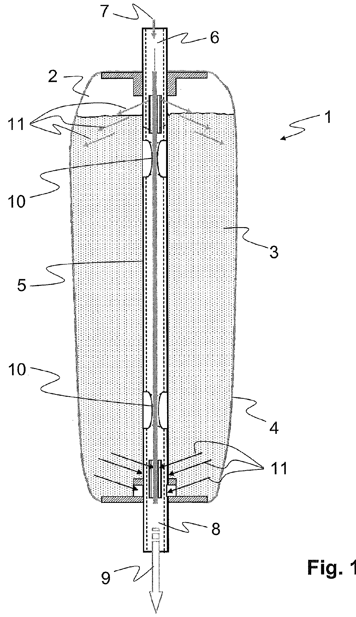
[0037]FIG. 1 shows a first preferred embodiment of the device according to aspects of the invention comprising a flexible receptacle or bag 1 which surrounds a cavity 2. The cavity 2 is completely or partially filled with an active substance 3 which usually is of granular consistency or exists in powder form. The outer skin of the bag 1 is a flexible outer shell 4 which surrounds the cavity 2 like a balloon or a hose, depending on the volume expansion. The outer shell 4 is supported by an inner (columnar) supporting element 5 which is connected to the flexible outer shell 4 in the vicinity of its first axial end and in the vicinity of its second axial end. The first end of the supporting element 5 extends through the outer shell 4, so that the projecting part of the supporting element 5 serves as an inlet 6 for a solvent 7 into the cavity 2 of the device. The supporting element 5 also has its second end extending through the flexible outer shell 4, so that this projecting part of th...


PUM


Abstract

Devices for preparing a liquid solution are disclosed. The device includes a receptacle defining a cavity for receiving at least one active substance to be dissolved, at least one inlet leading into the cavity for feeding at least one solvent into the cavity, and at least one outlet leading out of the cavity for discharging the liquid solution including the at least one active substance and the at least one solvent from the cavity. The cavity or the receptacle may include a flexible outer shell for enclosing the cavity and an inner, preferably columnar, supporting element for stretching the flexible outer shell between at least two points, the supporting element comprising the at least one inlet at its first end and the at least one outlet at its second end and being enclosed by the flexible outer shell to provide an axially rigid cartridge that can be used in currently customary dialysis machines comprising cartridge connection systems, which can be produced at low cost.

Description

CROSS REFERENCE TO RELATED APPLICATIONS[0001]This application claims priority to German application DE 10 2013 108 082.0 filed Jul. 29, 2013, the contents of such application being incorporated by reference herein.FIELD OF THE INVENTION[0002]The invention relates to a device for preparing a solution, in particular for use in or on an extracorporeal blood treatment machine such as a dialysis machine.BACKGROUND[0003]In dialysis machines, a dialysis liquid is prepared by dissolving a salt (bicarbonate) stored in a cartridge or by diluting a liquid concentrate with the addition of a liquid stored in a cartridge. The cartridge may be externally clamped in a special cartridge holder of the machine, via which the content of the cartridge is tapped in line with demand. This means that the cartridge holder usually has to fulfill two functions: the supporting of the cartridge as well as tapping the content of the cartridge.DESCRIPTION OF THE RELATED ART[0004]Cartridge holders for dialysis mac...

Claims


Application Information

Patent Timeline
Patent Type & Authority Patents(United States)
IPC IPC(8): B01F15/00A61M1/16B65D85/804
CPCB01F15/0085A61M1/167A61M1/1666A61M1/1668B65D85/8043B65D2231/004A61M2206/10A61M2206/20A61M2207/00B01F2215/0034A61M2205/7545A61M1/14A61M1/1656B65D85/8049B65D85/8052B01F35/513B01F2101/2202
Inventor ORSZULLOK, WILLY
Owner B BRAUN AVITUM
Why Eureka
Try Eureka