Active heating system for oil pipeline

a technology for heating systems and oil pipelines, applied in the field of oil pipelines, to achieve the effect of reducing the time to initiate a start up in the pipeline, reducing the energy expenditure, and shortening the priod of tim

Inactive Publication Date: 2006-01-03
COFLEXIP
View PDF7 Cites 17 Cited by
  • Summary
  • Abstract
  • Description
  • Claims
  • Application Information

AI Technical Summary

Benefits of technology

[0012]Another object of the invention is to enable such transmission through an initially chilled pipeline with minimalized expenditure of energy.
[0013]A further object is to provide such transmission by heating a pipeline efficiently and in a shorter priod of time than heretobefore.
[0014]According to the invention, a heating element in the form of at least one small diameter tube is inserted inside the main pipeline and is used to transfer hot water or other heated liquid form one end of the pipeline to the other. The tube is disposed in the pipe, rather than being disposed in the annulus between the outside carrier pipe and the inner pipe. The tube in the main pipe is exposed to the liquid contents in the pipe. All of the heat losses of the hot water tube heat both the pipe and its contents passing through the pipeline. This has the additional benefit that the normal contents carried through the pipeline and the main pipeline itself through which the tube passes insulate the hot tube so that all heat losses from the tube are useful for heating the contents of the pipeline and the pipeline itself, and there is minimal heat loss to the surrounding chilled subsea environment. This arrangement enables very long lengths of pipe to be maintained at a suitable temperature, and start up conditions in the pipeline can be maintained when the pipeline is not operating, especially as the pipeline had been heated. Further, the time to initiate a start up in the pipeline is significantly reduced.
[0015]A primary advantage of the proposed system is that is uses less energy to heat the pipeline and can also make use of the energy expended in heating the pipeline to extend over a greater distance along a pipeline than is true for traditional active heating systems. Compared to passive insulation systems, the invention can offer better performance, using less material and at lower cost. For example, this active heating system could cut the cost of heating the pipeline by avoiding the need for a surrounding carrier pipe (and the resulting annulus) and the need for expensive additional insulation for the heating system.
[0016]Hot water injected through the hot water tube in the pipeline heats the pipeline to reach the start up condition. Sufficient heating may take up to two days, which is a significant benefit in comparison with the ten days that is required to heat a pipe to its start up conditions with hot water either injected in and traveling along the annulus or with hot water in pipes that pass through the annulus.

Problems solved by technology

All of the heat losses of the hot water tube heat both the pipe and its contents passing through the pipeline.

Method used


Image

  • Active heating system for oil pipeline
  • Active heating system for oil pipeline
  • Active heating system for oil pipeline

Examples


Embodiment Construction

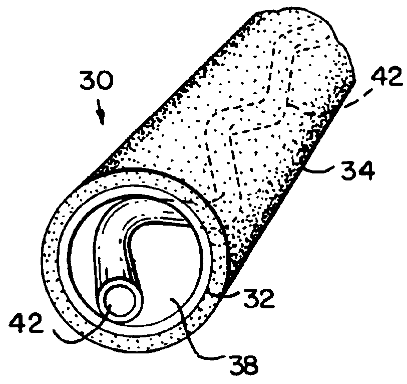
[0030]Turning to the embodiment of the invention disclosed in FIGS. 3 and 4, the proposed pipeline 30 includes an outer main pipeline 32 which may be insulated, as at the layer 34, or may not be insulated, and may be buried beneath the subsea surface, which could insulate it against heat loss outward. The pipeline may be rigid or flexible, as is known.

[0031]An elongate tube 36 passes through and along the main pipeline. It may be inserted during the pipeline fabrication process. The tube 36 may be inserted loosely in the pipe 32 and not be attached to the internal surface of the main pipeline. Alternatively, the tube may be affixed to the pipeline 32. It would be preferably attached at the ends of the pipeline. In interior surface 38, the tube may extend straight through the pipeline, or may have another shape therein, e.g., in a helix 42, as shown in FIG. 5. The helix may be normally sprung outward to rest on the pipeline interior surface or not, as selected.

[0032]In FIG. 3, the tu...


PUM


Abstract

A pipeline for transmitting oil or other substance which forms a solid residue such as wax when the substance is cooled, as in a subsea oil pipeline. Pass a tube through the interior of the pipeline, e.g., at the wall of the pipeline. Transmit heated liquid or water through the tube for heating the material being passed through the pipeline to a temperature which avoids or eliminates the solid residue and for heating the pipeline.

Description

[0001]Applicant claims the benefit of United States provisional application No. 60 / 163,928, filed Nov. 8, 1999.BACKGROUND OF THE INVENTION[0002]The present invention relates to an oil pipeline which is exposed to cold operating conditions, particular to a subsea pipeline which is subject to cold water temperature and also to a subsea pipeline exposed to elevated subsea pressure.[0003]Insulated oil pipeline is used in subsea transport of oil and in extraction of oil. In an oil field, when production initially starts and after production has halted for an interval, insulated subsea pipeline is at the cold water temperature. The reduced temperature of effluent in the pipe, such as residual oil and wax, will likely be reduced below the temperature of wax formation in the pipeline, which will lead to pipeline blockage, for example, between a subsea well and the receiving facility, such as a floating facility.[0004]There are several known solutions to the problem of a chilled pipeline.[00...

Claims


Application Information

Patent Timeline
Patent Type & Authority Patents(United States)
IPC IPC(8): F28D7/10
CPCF16L9/19E21B43/01F16L53/32
Inventor MOORE, ALEXANDER FRASER
Owner COFLEXIP
Why Eureka
Try Eureka