Optical receiver stub fitting

a technology for optical receivers and fittings, applied in the direction of cables, insulated conductors, instruments, etc., can solve the problems of limited anchoring strength of connectors and additional opening between clamping nuts, and achieve the effect of eliminating a possible moisture entry poin

Inactive Publication Date: 2000-02-29
SIECOR A DELAWARE
View PDF29 Cites 197 Cited by
  • Summary
  • Abstract
  • Description
  • Claims
  • Application Information

AI Technical Summary

Benefits of technology

are to provide a simple means for anchoring cable strength

Problems solved by technology

Although these connectors provide some anchoring and environmental sealing, the anchoring strength of the connector is limited due to the limited toler

Method used


Image

  • Optical receiver stub fitting
  • Optical receiver stub fitting
  • Optical receiver stub fitting

Examples


Embodiment Construction

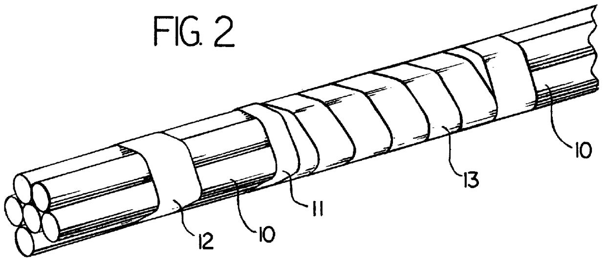
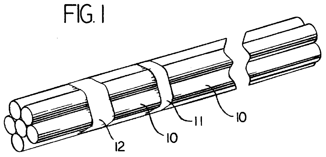
Nut 31 and grommet 30 are first placed over cable sheath 14. An array of flexible tubes 10 are bundled as shown in FIG. 1 by two strips 11,12 of heat shrinkable material which are preferably 1 / 4 inch wide. Tubes 10 are preferably made of a lightweight, low friction, highly flexible plastic such as Teflon.RTM. plastic. Strips 11, 12 are placed 3 / 16th of an inch apart. Strip 12 is located around 1 / 4 inch from one end of tubes 10.

After strips 11, 12 have cooled, spiral wrap material 13 is placed over the bundle of tubes 10, with one edge over strip 11 and the remainder proceeding in the direction opposite strip 12.

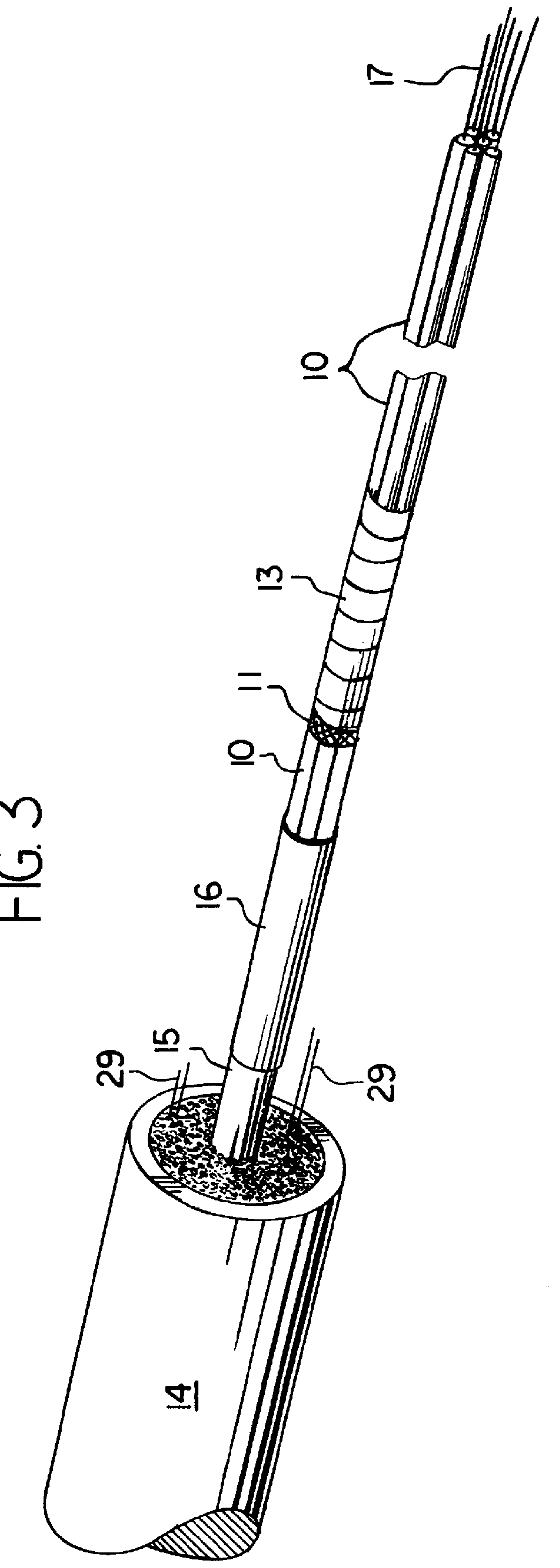
An optical cable is then prepared as shown in FIG. 3. After one end of cable sheath 14 has been stripped back, a buffer tube including optical fibers 17 extends a short distance. A cable strength member such as aramid yarn 29 also extend a short distance. Each optical fiber 17 is threaded through a flexible tube 10, with an optical connector 18 being placed on the distal end ...


PUM


Abstract

A cable assembly for attachment to an entry port of an optical enclosure. The assembly includes a plug for an end of an optical cable in a sealed housing having a single rigid tube and a single sealed nut. Connectorized optical fibers or an optical ribbon extend from the plug into the equipment enclosure.

Description

BACKGROUND OF THE INVENTIONFiber optic cable assemblies for connection to optical enclosures are currently available. Such assemblies must securely anchor the cable and be environmentally sealed. Certain connectors anchor the cable by means of a clamping mechanism requiring two nuts in addition to a rear sealing nut. Although these connectors provide some anchoring and environmental sealing, the anchoring strength of the connector is limited due to the limited tolerance of many cables to clamping. A further disadvantage of such connectors is the additional opening between the two clamping nuts which must be sealed.Objects of the invention are to provide a simple means for anchoring cable strength elements and to eliminate a possible moisture entry point.SUMMARY OF THE INVENTIONThe invention provides an improved cable assembly joining optical cables having optical fibers or optical fiber ribbons to optical enclosures such as patch panels or opto-electronic enclosures for optical netw...

Claims


Application Information

Patent Timeline
IPC IPC(8): G02B6/44G02B6/38G02B6/42
CPCG02B6/3897G02B6/4471G02B6/3878Y10T428/2964G02B6/4248
Inventor GIEBEL, MARKUS A.COOKE, TERRY L.
Owner SIECOR A DELAWARE
Why Eureka
Try Eureka