Concurrent engineering design tool and method

a technology of concurrent engineering and design tools, applied in the field of computer systems for automated concurrent engineering, can solve the problems of inability to reliably design subassemblies and abounding defective product designs, and achieve the effect of facilitating the selection of proper design approaches and reducing the time to market in the production of tools

Inactive Publication Date: 2000-03-07
STEVENS INSTITUTE OF TECHNOLOGY
View PDF9 Cites 83 Cited by
  • Summary
  • Abstract
  • Description
  • Claims
  • Application Information

AI Technical Summary

Benefits of technology

The tool fabrication process planner module uses the frame-based representation of the present invention to produce instructions to people or machines for the creation or assembly of a tool. By using the form/function parts of the present invention to describe tool and its manufacture, time to market is reduced in the production of tools. It is the natural extension of the concurrent part design methodology whereby the tool and its fabrication process are handled concurrently.
The present invention can suggest alternatives in the design process. The present invention facilitates the selection of proper design approaches. For example, if the user requires a join, the present invention lists possible choices, e.g., screws, clips, nails, etc., and if given enough information, may suggest a preferred approach. Further, taking other design information into account, once the desired join is selected, the system can make further design suggestions. Thus, if the user selects a screw, the system can inform the user of a preferr

Problems solved by technology

Without good part design, subassemblies cannot be reliably designed, and

Method used


Image

  • Concurrent engineering design tool and method
  • Concurrent engineering design tool and method
  • Concurrent engineering design tool and method

Examples


example

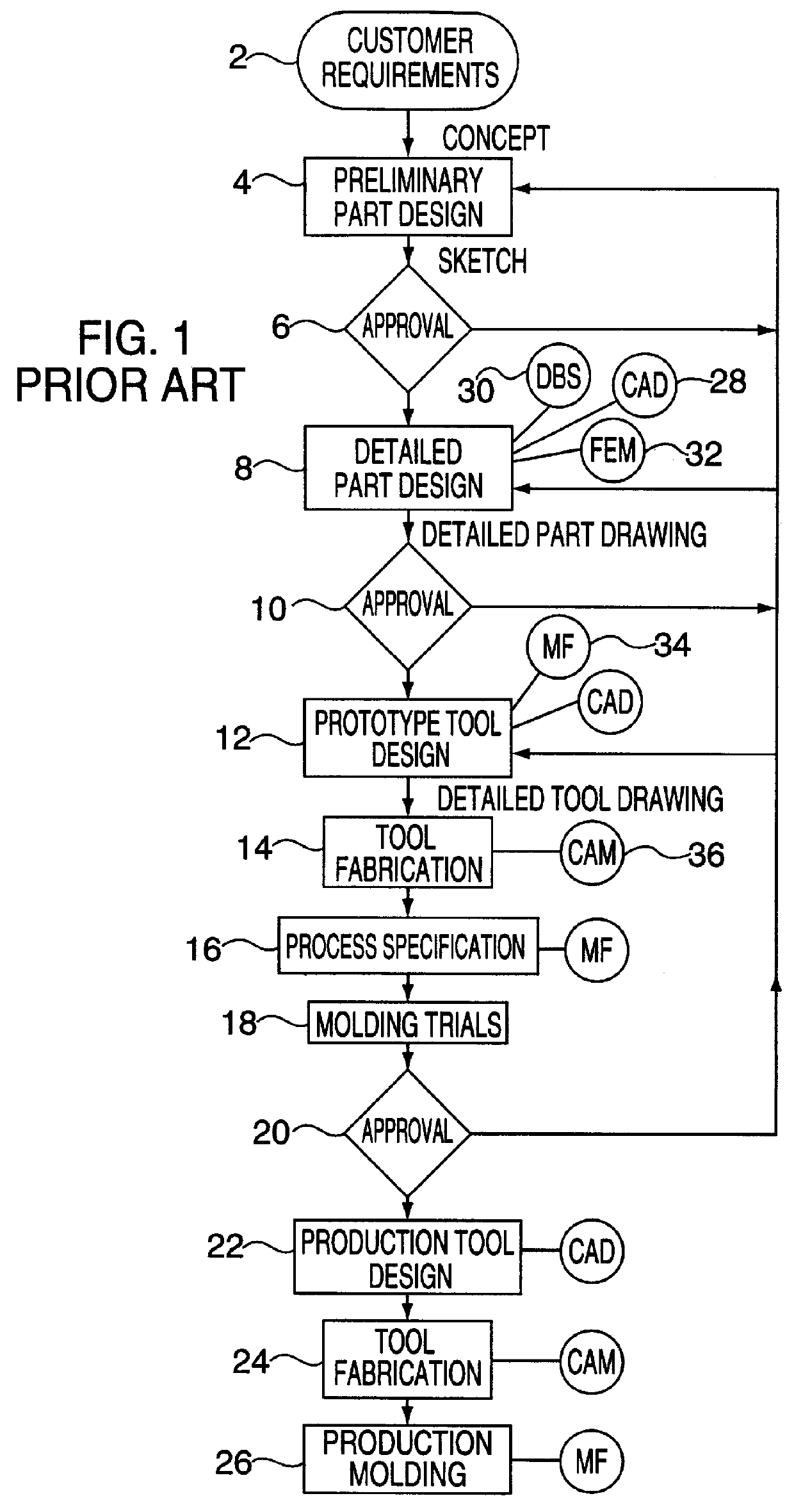
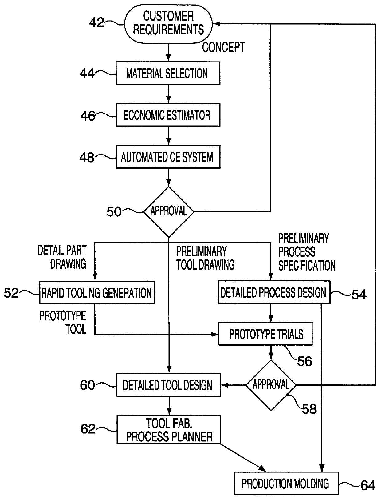
The power of the approach of the present invention in generating both configurational and geometric design is best illustrated by example, in this case, in the field of plastics. The example involves the development effort in the design of injection molded plastic parts. It is noted that this field of use is only an example, and the scope of the invention is not so limited.

Successful design or injection molded plastic parts requires extensive knowledge of material properties and behavior, tooling, injection conditions and other processing parameters. This complex relationship between plastic product design and the cost and quality of the product demands design experts with many years of experience who understand the interaction of these variables.

Polymer part production is, by its very nature, an activity that demands concurrency. Advanced polymer materials derive their properties from the material's microstructure, and this microstructure evolves from the processing steps that tran...


PUM

PropertyMeasurementUnit
Dimensionaaaaaaaaaa

Abstract

A computer-based engineering design system to design a part, a tool to make the part, and the process to make the part. The design system has a processor and a memory. The memory stores feature templates, each feature template being a representation of a primitive object having a form and a function. Each feature template is indexed by the function of the primitive object and includes a representation of a primitive geometric entity having the form of the primitive object. Each feature template can include information relating to a tool to make the primitive object and a process to make the primitive object. The design system also includes an input device for receiving a request to design the part. This request includes one or more predetermined functions that the part performs. A core design module, executable by the processor, designs the part, the tool to make the part and process to make the part by accessing the plurality of feature templates in the memory to locate one or more primitive objects that perform the one or more predetermined functions.

Description

FIELD OF THE INVENTIONThe present invention is directed to a computer system for automated concurrent engineering, and more particularly, to a method and apparatus for the concurrent design of parts, tools and processes.BACKGROUND OF THE INVENTIONConcurrent engineering aims to integrate product design and manufacturing cycles in a systematic way to facilitate the swift, cost-effective progression of new products from raw concept to end customer.Traditionally, when designing a new product, a team of designers usually participate in what is known as a product development cycle. In general terms, the first stage in designing a new product is that of concept design, in which overall needs and aims are addressed.Next is the initial design stage. The initial design stage comprises steps of designing the part, then choosing the materials and determining the process to make the part, then designing the tool to make the part. For example, if the part is to be a computer keyboard, first the s...

Claims


Application Information

Patent Timeline
IPC IPC(8): B29C33/38G05B19/4097G06F17/50
CPCB29C33/3835G05B19/4097G06F17/50G05B2219/31398G05B2219/35044G05B2219/35081G06F30/00Y02P90/02
Inventor SEBASTIAN, DONALD H.PRATT, STEVENMUTHUSWAMY, SIVAKUMARKNIEP, DAVIDMANOOCHEHRI, SOURANKOLODZIESKI, SCOTT
Owner STEVENS INSTITUTE OF TECHNOLOGY
Why Eureka
Try Eureka