Fiber-optic lighting system

a fiber optic lighting and fiber optic technology, applied in the direction of landing aids, light support devices, aircraft crew accommodation, etc., can solve the problems of few lamps needed to illuminate the main cabin interior, and achieve the effects of reducing the potential for injury and fire, reducing the weight, and reducing the power consumption system

Inactive Publication Date: 2000-04-04
ZIADI BOUCHAIB
View PDF15 Cites 14 Cited by
  • Summary
  • Abstract
  • Description
  • Claims
  • Application Information

AI Technical Summary

Benefits of technology

The inventor has succeeded in developing a fiber-optic lighting system for illuminating the interior of aircraft which offers reduced costs and reduced weight, as well as reduced risk of injury, fire and electrical shock. In addition, the system of the present invention has an increased reliability and a decreased potential for electro-magnetic and radio frequency interference.
The aircraft interior lighting system of the present invention includes a power supply connected to a high intensity light source. Both the power supply and high intensity light source are remotely located away from the main cabin interior thereby reducing the potential for injury and fire hazard in the main cabin. Elongated fiber-optic light guides extend from the light source to various light fixtures located throughout the aircraft cabin interior. The light fixtures are comprised of reflectors, lenses and globes and do not contain lamps. As a result, few, if any, lamps are needed to illuminate the main cabin interior. Thus, electricity need not be transmitted throughout the cabin interior to power the lamps as in earlier lighting systems.
The present invention overcomes many of the problems inherent with traditional aircraft lighting systems. In particular, the lighting system of the present invention is a relatively low weight and low power consumption system because fewer lamps are required. In addition, the heat generated by the system is confined to a remote location which is spaced from passengers and is isolated from any areas of the aircraft where conventional lighting could present a fire hazard. Thus, the potential for injury and fire is significantly reduced and confined. Further, because fewer lamps are used in the lighting system, less maintenance is required with the present lighting system than with conventional aircraft lighting systems. In addition, the lighting system has an increased durability over the prior art systems which has the advantage of reducing maintenance costs as well. Still further, the power distribution network of the lighting system of the present invention is significantly smaller than fluorescent lighting system power distribution networks so that the potential for electro-magnetic interference and radio frequency interference is significantly reduced.

Problems solved by technology

As a result, few, if any, lamps are needed to illuminate the main cabin interior.

Method used


Image

  • Fiber-optic lighting system
  • Fiber-optic lighting system
  • Fiber-optic lighting system

Examples


Embodiment Construction

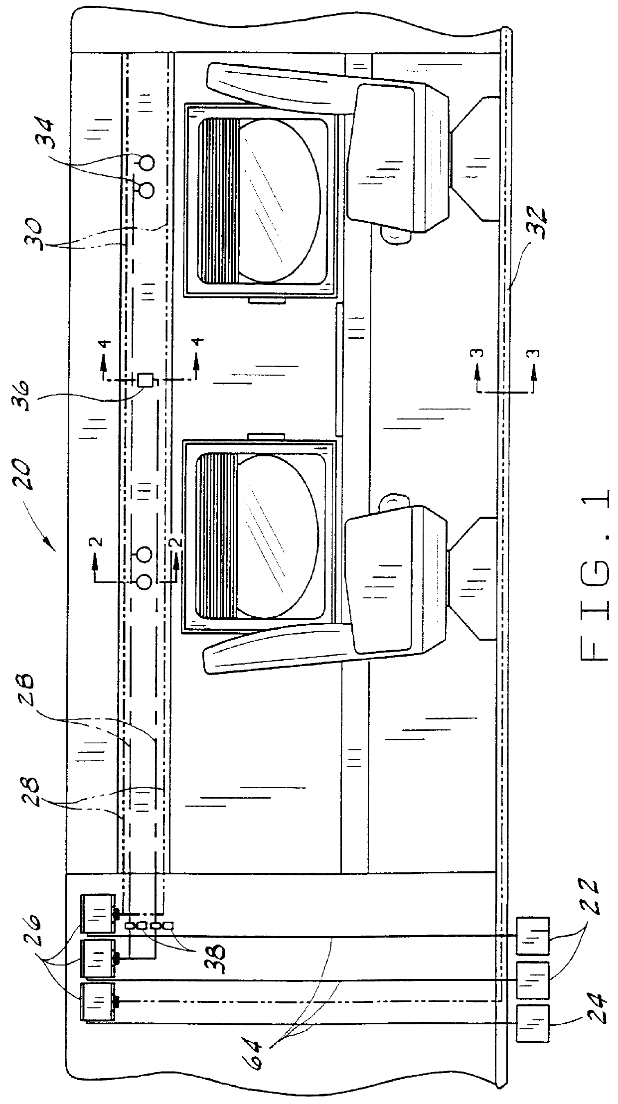
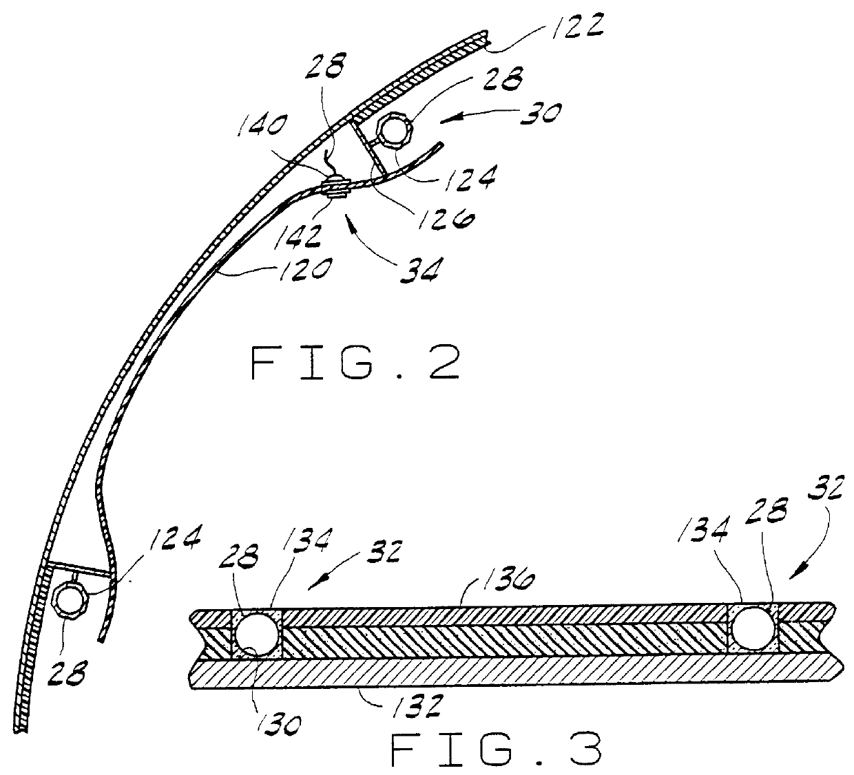
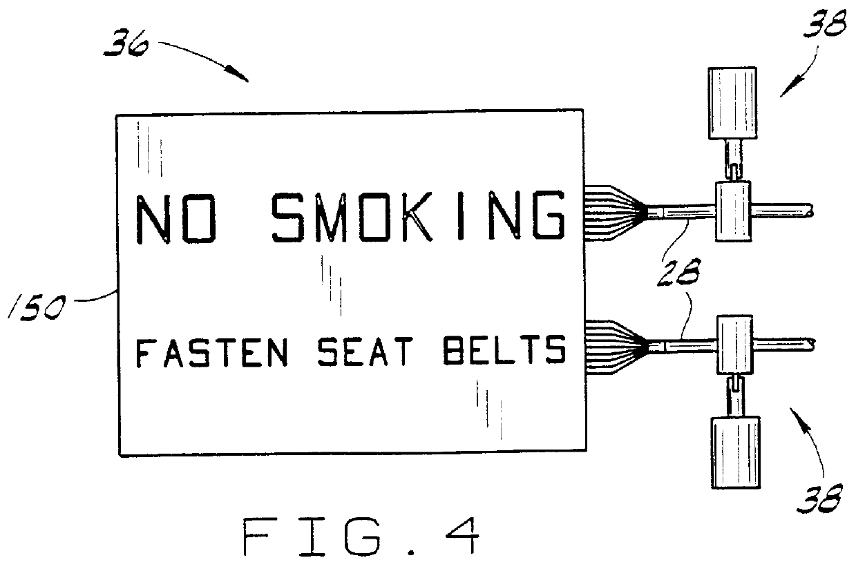
Although equally well suited for other environments where lighting is necessary, the preferred embodiment of the present invention is intended for use in the interiors of passenger aircraft as shown in FIG. 1. The fiber-optic lighting system 20 is generally comprised of remote power supplies 22, 24 connected to high intensity light sources 26. Light guides or fiber-optic cables 28 extend from the light sources 26 to various light fixtures 30, 32, 34, 36 throughout the cabin. These light fixtures may be used to replace most any type of light fixture commonly used in aircraft interiors including valance mounted light fixtures 30 used for general cabin lighting and reading light fixtures 34 as best shown in FIG. 2. In addition, the light fixtures include emergency floor strip light fixtures 32 and passenger signal indicators as shown in FIGS. 3 and 4, respectively. Switches 38 may be placed in series with the light guides 28 to alternately permit or inhibit light from reaching the ligh...


PUM


Abstract

A fiber-optic lighting system is powered by a power supply connected to a high intensity light source which generates a beam of light. A first elongate light guide extends between a first end positioned within the beam of light and a second end positioned adjacent a lamp reflector. A second elongate light guide which is configured to emit light from a side also extends from a first end positioned within the beam of light. An elongate light fixture is positioned along the second light guide for directing light emitted from the side of the light guide.

Description

BACKGROUND OF THE INVENTION1. Field of the InventionThe present invention is directed to a fiber-optic lighting system. In particular, the preferred embodiment of the present invention is intended to light the cabin interior of commercial passenger aircraft by transmitting light from a remote light source to individual light fixtures throughout the aircraft.2. Description of the Related ArtSince people have been traveling by aircraft at night, there has been a need to light aircraft cabins to enable passengers to see. In the past, conventional incandescent and fluorescent lighting systems have been used to provide aircraft lighting. However, as will be explained below, these systems have numerous drawbacks.The primary drawback associated with conventional lighting systems is that they require that many lamps be used throughout the aircraft. Each lamp increases the weight of the aircraft. Although increases in weight are undesirable in most apparatus, weight increases are especially ...

Claims


Application Information

Patent Timeline
Patent Type & Authority Patents(United States)
IPC IPC(8): B60Q3/02B60Q3/00B64D11/00F21V8/00G02B6/35
CPCB60Q3/005B60Q3/025B60Q3/0253B60Q3/0256B64D11/00G02B6/0001G02B6/0005G02B6/353B64D2011/0038Y02T50/46G02B6/3552G02B6/3572G02B6/3574B64D2011/0053B60Q3/66B60Q3/43B60Q3/44B60Q3/46Y02T50/40
Inventor ZIADI, BOUCHAIB
Owner ZIADI BOUCHAIB
Why Eureka
Try Eureka