Battery plates having rounded lower corners

a battery plate and lower corner technology, applied in the field of battery plate manufacturing, can solve the problems of reducing battery life, short circuit of battery, and no process for producing rounded corners on such battery plates

Inactive Publication Date: 2000-06-13
JOHNSON CONTROLS TECH CO
View PDF18 Cites 30 Cited by
  • Summary
  • Abstract
  • Description
  • Claims
  • Application Information

AI Technical Summary

Benefits of technology

A process for cutting a moving strip to form a series of plates, such as battery plates, initially involves transporting the strip past a divider having a rotary cutter with a first set of blades extending radially therefrom configured to cut the strip into the plates, and a second set of radial blades for cutting individual pieces from the strip. As the blades cut the strip to form the plates and pieces, a vacuum system applies suction to draw the pieces cut from the strip inwardly into the cutter through holes in the cutter, and then out of the cutter. The holes are each located adjacent one of the corresponding cutter blades of the second set and are shaped and positioned to permit the cut-away piece to pass through. In a preferred embodiment, the vacuum system includes a pair of vacuum manifolds that apply suct

Problems solved by technology

However, the bottom corners on the battery plates are sharp, and will snag and tear the separator material between the positive and negative plates, causing an electrical short within the battery and reducing battery life.
Bending or vibration of the plate disposed in the envelope during assembly or use can also cause tearing, and the problem is not confined to envelope-style separators.
Use of battery plates with rounded bottom corners would eliminate the snag and tearing of s

Method used


Image

  • Battery plates having rounded lower corners
  • Battery plates having rounded lower corners
  • Battery plates having rounded lower corners

Examples


Embodiment Construction

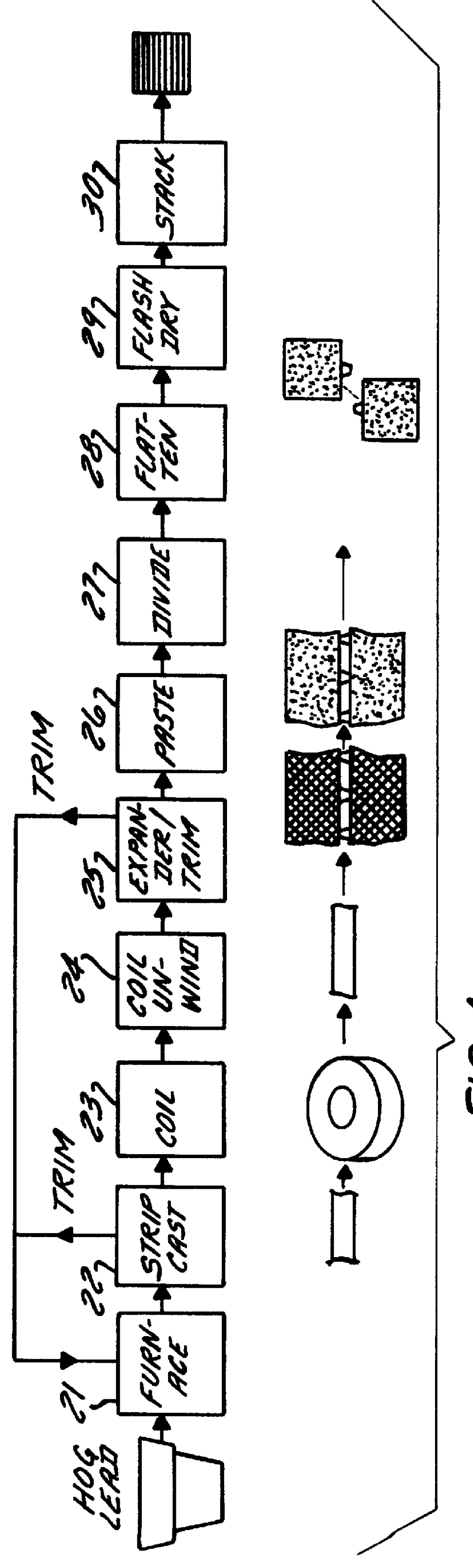
Referring to FIG. 1, the process according to the invention is shown in relation to the other steps conventionally used in a continuous process for making lead-acid battery plates. The known process for making such plates includes an initial step 21 of melting hog lead in a furnace, followed by a step 22 of feeding molten lead alloy to a strip caster. Trim from the caster is recycled to the furnace. The strip is coiled (23) on a winder, and coils of lead alloy strip are stored for later use.

To form a battery grid, the coil is unwound (24) and the free end is fed through an expander that cuts, slits and stretches (25) the strip to form a mesh-like pattern of grid elements. See, for example, the expanders described in U.S. Pat. Nos. 4,315,356 and 4,291,443 assigned to Cominco Ltd., the contents of which are incorporated herein by reference. Trim from the expander is recycled to the furnace. The expanded strip is then pasted (26) by a conventional paster, and then fed to the divider ac...


PUM

PropertyMeasurementUnit
Shapeaaaaaaaaaa
Electrical conductoraaaaaaaaaa

Abstract

A process for cutting a moving strip to form a series of plates, such as battery plates, includes the initial step of transporting the strip past a rotary divider including a cutter having radial blades configured to cut the strip into the plates. The cutter further has a set of blades for cutting individual pieces from the strip, which pieces are not part of the plates. As the cutter blades cut the strip to form the plates and pieces, a vacuum system applies suction to draw the pieces cut from the strip inwardly into the cutter through holes in the cutter, and then out of the cutter. The holes are each located adjacent each one of the corresponding blades and are shaped and positioned to permit the cut-away piece to pass through. In a preferred embodiment, the vacuum system includes a pair of vacuum manifolds that apply suction at opposite ends of the cylindrical cutter. An apparatus for carrying out the foregoing process accordingly includes a rotary divider as described above provided with a vacuum system. Battery plates made according to the foregoing process are improved in that the two lower corners have a rounded shape lacking a sharp edge which tends to tear an adjacent separator. Such a plate may be inserted bottom end first into a separator envelope to form a plate element for use in a lead-acid battery.

Description

TECHNICAL FIELDThe present invention relates to the manufacture of plates from a moving strip by cutting the strip, particularly to the manufacture of battery plates for use in lead-acid batteries.BACKGROUND OF THE INVENTIONA plate for a lead-acid battery is conventionally made by applying a battery paste to a conductive support such as a lead alloy grid. The paste is made from lead oxide, sulfuric acid and water. The lead oxide reacts with the sulfuric acid to form mono-, tri- or tetrabasic lead sulfate(s). Dry additives such as fiber and expander may be added. The mixture is then dried and water is re-added to form a paste of the desired consistency. The paste is applied to the lead grid, and the pasted plates are then flash-dried and cured at an elevated temperature and humidity to oxidize free lead and adjust the crystal structure of the plate. After curing, the plates are assembled into batteries and electrochemically formed by passage of current to convert the lead sulfate or ...

Claims


Application Information

Patent Timeline
IPC IPC(8): H01M4/72H01M4/82H01M4/73H01M4/64H01M4/16H01M4/20
CPCH01M4/16H01M4/20H01M4/82H01M4/73Y02E60/126Y02E60/10Y10T83/207Y10T83/222Y10T83/483Y10T83/658
Inventor BINDER, RICHARD R.W.CANTILLON, DANIEL J.SCHNEIDER, JEFFREY J.
Owner JOHNSON CONTROLS TECH CO
Why Eureka
Try Eureka