Source of electrical power for an electric vehicle and other purposes, and related methods

a technology for electric vehicles and electrical power, applied in the field of electric power sources, can solve the problems of limited power supply, low discharge/recharge power requirements of battery presently available, and unsatisfactory prior battery technology for high discharge and high recharge power requirements, etc., to minimize the various resistances in the electrode structure, improve discharge/recharge properties, and improve the effect of life cycl

Inactive Publication Date: 2000-05-16
BIPOLAR TECH
View PDF18 Cites 55 Cited by
  • Summary
  • Abstract
  • Description
  • Claims
  • Application Information

AI Technical Summary

Benefits of technology

The micro thin sheet technology embraces one or more of certain basic characteristics, i.e. enhanced power and capacity due to: (1) the thinness of the electrode-forming sheet; (2) the high degree of active (corroded) material created on the sheet; (3) the presence of undulations, corrugations, or up and down irregularities in the sheet; (4) the spiral orientation of positive and negative separated thin sheet electrodes; (5) the combination of the thin sheet technology to bipolar battery technology; (6) implementation of microcorrugations or micro-irregularities in a thin sheet of foil; (7) the creation of a greater amount and greater depth of active material on a thin sheet electrode; (8) provision of electrochemically-caused high microporosity in a thin sheet electrode; (9) facilitating a high degree of electrolyte accessibility to electrodes; (10) elimination of the need to and costs associated with rinsing metal solubilizing agent from pores in thin metal sheets for use as battery electrodes; (11) concurrent and conjoint formation of positive and negative electrodes; (12) use of thin sheet electrode-to-tab-to-terminal technology; and (13) thin sheet bipolar battery technology.
A further object is to provide novel thin sheet electrodes that minimize the various resistances in the electrode structure.

Problems solved by technology

Because of a number of fundamental deficiencies, including but not limited to ionic resistance and electronic resistance within the cell, prior battery technologies have proven to be unsatisfactory for high discharge and high recharge power requirements including those imposed in the operation of an all-electric or hybrid electric vehicle.
No battery presently available can approach the power requirements (especially charging power) for the parallel-configured hybrid vehicle.
The limitations in power are not necessarily due to the fundamental electrochemistry of the battery systems, but instead are often due to certain design constraints of the batteries, particularly the electrodes.
Still, the performance of prior spirally-wound lead-acid cells is not adequate for many load-levelling applications requiring high rate charging and discharging, such as hybrid electric vehicles.
Cycle life is short due to the solubility of both zinc and silver, and the aggressive action of silver on separator materials.
The cost is obviously high, such that its application is usually limited to military and aerospace purposes, where energy density is of primary importance, and cost is not.
The resulting electrodes proved very durable, but suffered from low specific capacity (A.multidot.hr / cm.sup.2).
The processing of Plante flat plate batteries are typically costly and time intensive compared to pasted electrode batteries.
Flushing of potassium perchlorate adds significantly to the time and cost requirements.

Method used


Image

  • Source of electrical power for an electric vehicle and other purposes, and related methods
  • Source of electrical power for an electric vehicle and other purposes, and related methods
  • Source of electrical power for an electric vehicle and other purposes, and related methods

Examples


example

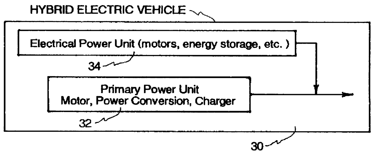
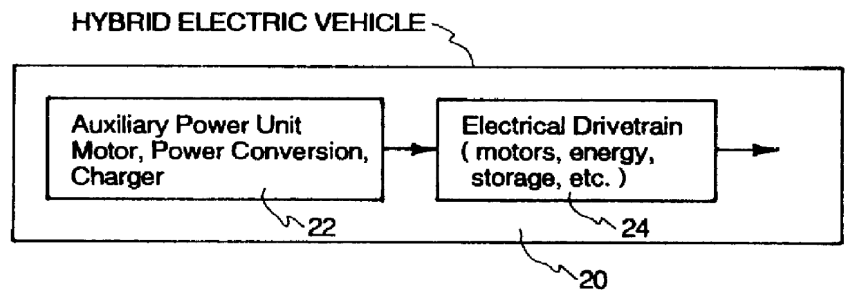
The following examples demonstrate the production of bipolar electrodes and spirally-wound electrodes for lead-acid batteries. The resulting battery in each case is particularly suitable for use in HEVs. Joint studies by the HEV program by Department of Energy and various automotive manufacturers have demonstrated that, while the existing battery designs approach most requirements for HEVs, there is still a serious difficulty in meeting the requirements for peak discharge power and regeneration power. The power limitations are even more pronounced when considered for use in parallel-configured hybrid vehicles of FIG. 2. These vehicles require a battery pack which is smaller in size, and yet can be both discharged and recharged at rates comparable to those specified for the series-configured hybrid of FIG. 1.

The limitations in power are not due to the fundamental electrochemistry of the battery systems, but instead are due to the configurations and constraints of prior batteries, par...

example i-- bipolar battery

Example I--Bipolar Battery

In general, a bipolar battery of this invention comprises bipolar electrodes, with separator layers placed between electrodes which are laid upon one another like a stack of pancakes. A bipolar electrode of a thin, flat conductive material (such as a metal foil), with a positive active electrode material deposited on one face, and a negative electrode placed on the opposite face. A bipolar cell comprises the positive electrode side of one bipolar electrode, the negative electrode side of a second closely spaced bipolar electrode and the electrolyte between the two. On the ends of the battery are placed single-sided (monopolar) electrodes. Each individual cell is normally sealed to prevent electrolyte leakage.

This example demonstrates the manufacture and performance of bipolar electrodes made in accordance with the present invention. For comparison purposes, a conventional bipolar electrode is illustrated in FIG. 5. The bipolar electrodes of the invention ca...

example ii--

Spirally-Wound Battery

This example demonstrates the manufacturing viability and performance characteristics of a spirally-wound battery made in accordance with the present invention. This configuration of the invention meets all of the power requirements of the HEVs, both series and parallel-configured.

Electrodes were made by taking strips of corrugated lead sheet and electroforming the corrugated lead using a process embodying the principles of the invention. See FIG. 11. The electrodes were then sandwiched with strips of separator material, and the combination spirally wound into a cylindrical shape. See FIG. 12. After placing the roll into a cylindrical container (FIG. 13) and making appropriate electrical connection, electrolyte was placed in the cell and the cell was sealed.

The lead sheets were given high and low surface irregularities. Lead foil may be passed through rollers with small parallel ridges in their surfaces to create corrugations by forming grooves in the lead foil...


PUM

PropertyMeasurementUnit
thicknessaaaaaaaaaa
sizeaaaaaaaaaa
depthaaaaaaaaaa

Abstract

Microthin sheet technology is disclosed by which superior batteries are constructed which, among other things, accommodate the requirements for high load rapid discharge and recharge, mandated by electric vehicle criteria. The microthin sheet technology has process and article overtones and can be used to form thin electrodes used in batteries of various kinds and types, such as spirally-wound batteries, bipolar batteries, lead acid batteries, silver / zinc batteries, and others. Superior high performance battery features include: (a) minimal ionic resistance; (b) minimal electronic resistance; (c) minimal polarization resistance to both charging and discharging; (d) improved current accessibility to active material of the electrodes; (e) a high surface area to volume ratio; (f) high electrode porosity (microporosity); (g) longer life cycle; (h) superior discharge / recharge characteristics; (j) higher capacities (Axhr); and k) high specific capacitance.

Description

The present invention relates to electrical batteries in general and more particular to improved sources of electrical power for an electric vehicle and other purposes, and related methods.In its most elemental way, a source of electrical power is typically a battery which may comprise one or more battery cells. Each cell typically comprises encapsulized electrolyte and positive and negative electrodes. During cell operation, electrons move through the solid electrode material, to the electrolyte / electrode interface. There, a faradaic (charge-transfer) reaction occurs, which transfers the charge from electrons to electrolyte species. Ions then flow through the electrolyte to the opposite electrode, where another faradaic reaction takes place, liberating electrons into the solid electrode material. Electrons then flow from the electrode to the external load connected to the battery.Because of a number of fundamental deficiencies, including but not limited to ionic resistance and elec...

Claims


Application Information

Patent Timeline
Patent Type & Authority Patents(United States)
IPC IPC(8): H01M10/06H01M10/24H01M2/28H01M2/20H01M10/04H01M2/26H01M4/14H01M10/12H01M10/28H01M10/42H01M4/04H01M10/44H01M10/32H01M50/505H01M50/541
CPCH01M2/204H01M4/0447H01M4/14H01M10/0431H01M10/125H01M10/286H01M2/28Y10T29/49115H01M10/06H01M10/32H01M10/446Y02E60/124Y02E60/126Y02T10/7016Y10T29/49108Y10T29/10Y02E60/10Y02P70/50H01M50/505Y02T10/70
Inventor LAFOLLETTE, RODNEY M.
Owner BIPOLAR TECH
Why Eureka
Try Eureka