Current collector structure and methods to improve the performance of a lead-acid battery

a lead-acid battery and current collector technology, applied in the field of current collector structure and methods to improve the performance of lead-acid batteries, can solve the problems of limiting the actual specific energy of lead-acid batteries, imposing challenging performance demands on battery technologies, and low utilization efficiency of active mass, so as to enhance the cyclability of subsequent high surface area electrodes, the effect of improving performan

Inactive Publication Date: 2006-06-13
POWER TECH INC
View PDF2 Cites 58 Cited by
  • Summary
  • Abstract
  • Description
  • Claims
  • Application Information

AI Technical Summary

Benefits of technology

[0009]The present invention relates to methods of improving the performance, especially cycling performance, of lead-acid batteries by using current collector structures based on light-weight, porous, open pore, high specific surface area (e.g. >500 m2 / m3) substrates coated with a lead-tin alloy. More specifically it relates to the use of lead-tin alloys deposited on lightweight, open pore substrates such as carbon or aluminum to dramatically enhance the cyclability of the subsequent high surface area electrode for use as an anode and / or cathode in lead acid batteries while achieving all of the prior art mentioned advantages of high surface area porous electrodes, for example reticulated electrodes.

Problems solved by technology

Continuous developments on the application side, for instance in the area of electric vehicles and hybrid electric vehicles (EV and HEV), impose challenging performance demands on battery technologies in general and lead acid batteries in particular.
It is well known that the low utilization efficiency of the active mass, especially on the positive electrode, in conjunction with the heavy weight of the lead current collectors, limits the actual specific energy of the lead-acid battery.
Such a porous lead electrode would lead to electrochemical cells and accumulators which produce more power per unit of weight and also present very low electrical resistance.”
Consequently, if a battery had been assembled with the above described electrodes, the corresponding capacity would have been extremely low, in the range of 4.5 mAh, insufficient for practical use.
Furthermore, the battery structure described by Czerwiński and Zelazowska is not rechargeable in sulfuric acid, which is the operational electrolyte of lead-acid batteries, since the recommended active material generation procedure required alkaline and nitrate based electrolyte.
Clearly, it was not envisaged to paste active materials onto the reticulated substrate in order to create a high capacity, rechargeable battery.
This prior art does not teach methods for using such a structure to improve the cycle life and performance of a lead acid battery and does not envisage the use of non-metallic electrically conductive substrates such as reticulated carbon to reduce battery weight.

Method used


Image

  • Current collector structure and methods to improve the performance of a lead-acid battery
  • Current collector structure and methods to improve the performance of a lead-acid battery
  • Current collector structure and methods to improve the performance of a lead-acid battery

Examples


example 1

Manufacturing of the Reticulated Current Collector

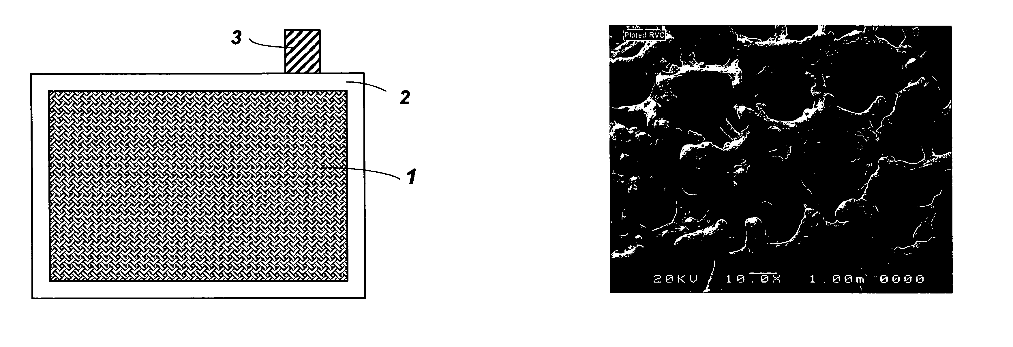
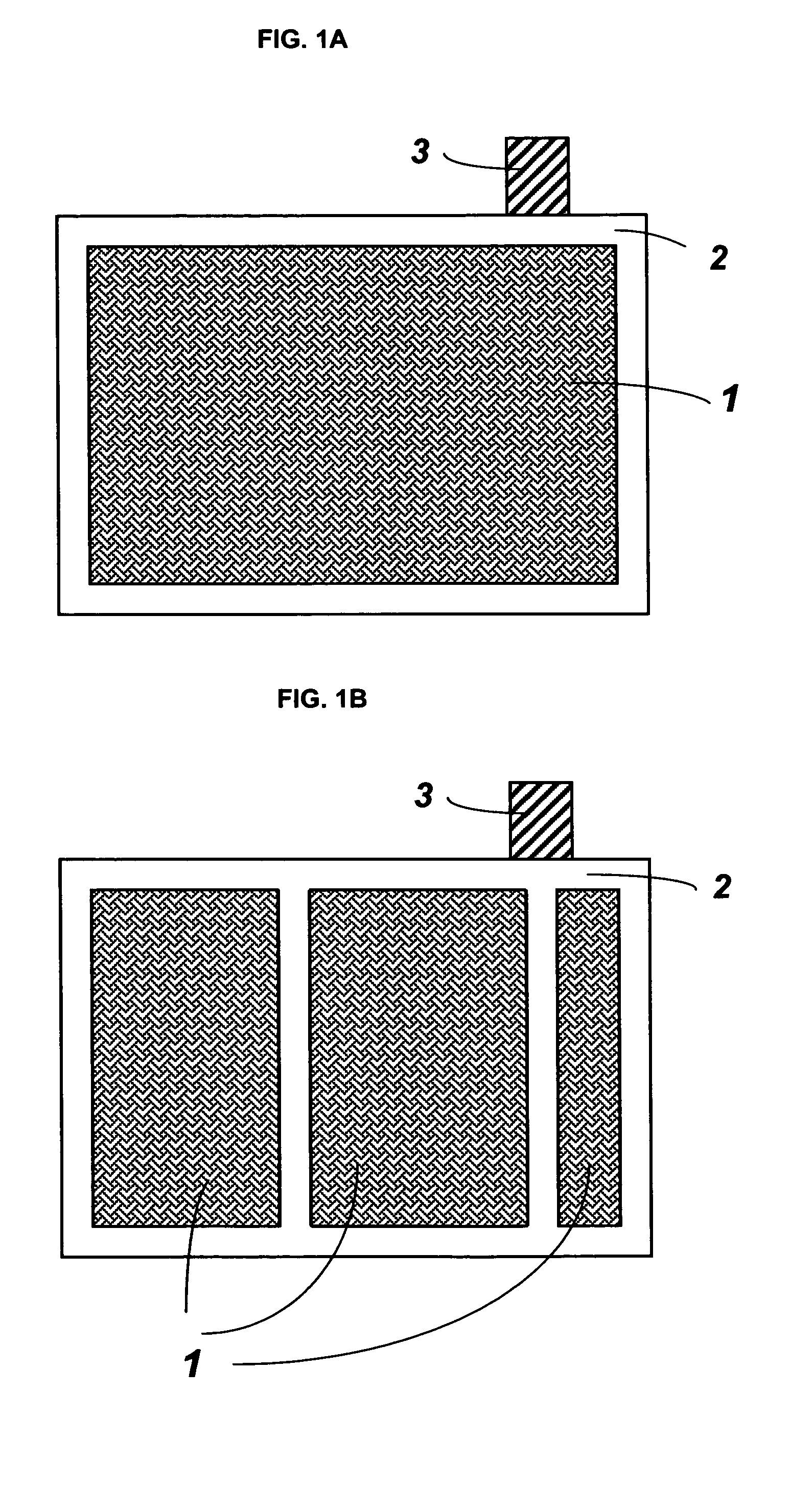
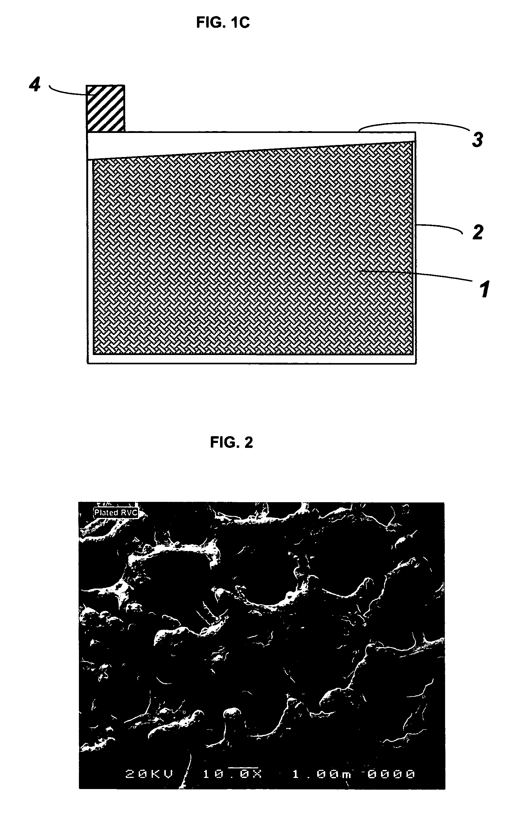
[0025]In one embodiment of the present invention, reticulated vitreous carbon (RVC) slabs with 20 and 30 pores per inch (about 8 and 12 pores per centimeter, respectively) were used as substrates for grid manufacturing. The RVC slab having dimensions of: 15.2 cm×15.2 cm×12.8 mm (height×width×thickness) was sliced to a preferred thickness of about 3.5 mm, using a steel cutter. After slicing, the height and width of the carbon slab was adjusted to the size needed for the particular battery. One of the commonly employed current collector sizes is 12.7 cm×12.7 cm (height×width).

[0026]Following size adjustment, the vitreous carbon substrate was uniformly coated with a layer of lead-tin alloy. A variety of methods can be used for the deposition of lead-tin alloys on carbon based substrates, such as electroplating and vacuum deposition. In the present invention electroplating (or electrodeposition) was chosen to apply the lead-alloy coating...

example 2

Effect of Coating Composition on the Battery Cycling Performance

[0033]In order to compare the performance of the pure lead and lead-tin alloy reticulated collectors, two flooded, single cell, 2 V, batteries were assembled, equipped with pasted plates using pure lead and lead-tin (1% by weight of tin) coated collectors, respectively. The pure lead and lead-tin coated collectors were manufactured according to the procedure described in Example 1. The following table summarizes the plating recipes and plating conditions.

[0034]

TABLE 1Electroplating conditions.LeadLeadLead-TinLead-TinCoatedCoatedCoatedCoatedPositiveNegativePositiveNegativeRecipe per one liter of500 ml of 50% by74 ml of 50% byelectrolyteweight Pb(BF4)2; 410weight Sn(BF4)2, 510ml of deionized water,ml of 50% by weight27 g of H3BO3, 90 mlPb(BF4)2; 376 ml ofof HBF4, and 3 g ofdeionized water, 27 gpeptoneof H3BO3, 40 ml ofHBF4 , and 1 g ofgelatinCurrent Density (A / m2)570570570570Plating Temperature25252525(° C.)Plating Time (...

example 3

Performance Comparison Between Batteries Employing Book-Mould Grids and Electroplated Reticulated Vitreous Carbon Current Collectors

[0037]The comparative nominal capacities, Peukert diagram, for the performance limiting positive electrode in the case of two flooded single-cell 2 V batteries employing book-mould and lead-tin (1% by weight of tin) electrodeposited RVC collectors, respectively, is shown by FIG. 5. Both battery types were pasted, assembled and formed under identical conditions. The lead-tin electrodeposited reticulated grids were prepared according to the method described in Example 1 and Example 2. The employed discharge currents corresponded to discharge rates between 24 to 2 h for the positive limited electroplated RVC collector battery and 12 to 2 h for the book-mould grid battery, respectively (FIG. 5).

[0038]Discharging the two batteries at a current of 27.5 A / kgPAM the specific discharge capacity of the positive plate using the electrodeposited RVC collector was 1...


PUM

PropertyMeasurementUnit
surface areaaaaaaaaaaa
thicknessaaaaaaaaaa
specific energyaaaaaaaaaa

Abstract

A battery, a battery electrode structure, and methods to make the same. The product and method comprise applying a layer of lead-tin containing alloy to substrates for anodes or cathodes for lead-acid batteries, in which the substrates are porous or reticulated.

Description

PRIORITY OF CONTINUING APPLICATION[0001]This application is a continuation of co-pending application PCT / US02 / 30607 and claims priority to U.S. Provisional Patent Application 60 / 325,391 filed on Sep. 26, 2001.FIELD OF THE INVENTION[0002]This invention relates generally to lead-acid battery electrodes and particularly to high surface area electrodes which improve the performance of lead-acid batteries in one or more ways alone or in combination such as: specific discharge capacity, positive active mass utilization, and discharge / recharge cyclability.BACKGROUND OF THE INVENTION[0003]The lead-acid battery in its various configurations is a time-honoured power source for diverse applications such as starting-lighting-ignition (SLI), uninterrupted power supply (UPS) and motive power. Continuous developments on the application side, for instance in the area of electric vehicles and hybrid electric vehicles (EV and HEV), impose challenging performance demands on battery technologies in gen...

Claims


Application Information

Patent Timeline
Patent Type & Authority Patents(United States)
IPC IPC(8): H01M4/66H01M4/74C25D3/56H01M4/20H01M4/56H01M4/58H01M4/68H01M4/80
CPCC25D3/56H01M4/20H01M4/661H01M4/663H01M4/74H01M4/80H01M4/685Y10T29/10Y02E60/126Y02E60/10
Inventor GYENGE, ELODJUNG, JOEYSNAPER, ALVIN A.
Owner POWER TECH INC
Why Eureka
Try Eureka