Multilevel cascade voltage source inverter with seperate DC sources

Inactive Publication Date: 2001-04-03
LOCKHEED MARTIN ENERGY SYST INC
View PDF16 Cites 62 Cited by
  • Summary
  • Abstract
  • Description
  • Claims
  • Application Information

AI Technical Summary

Benefits of technology

Accordingly, it is an object of the present invention to provide a new and improved multilevel cascade voltage source inverte

Problems solved by technology

Delivering power from a power generating station to the ultimate power consumers over long transmission lines can be very costly for an electric utility.
The major problem of using this transformer coupling approach resides in the transformer as a function of harmonic neutralizing magnetics.
(a) is the most expensive equipment in the system;
(b) produces approximately 50% of the total system losses;
(c) occupies approximately 40% of the system layout; and
(d) causes difficulties in system control due to DC magnetizing and surge ove

Method used


Image

  • Multilevel cascade voltage source inverter with seperate DC sources
  • Multilevel cascade voltage source inverter with seperate DC sources
  • Multilevel cascade voltage source inverter with seperate DC sources

Examples


embodiment

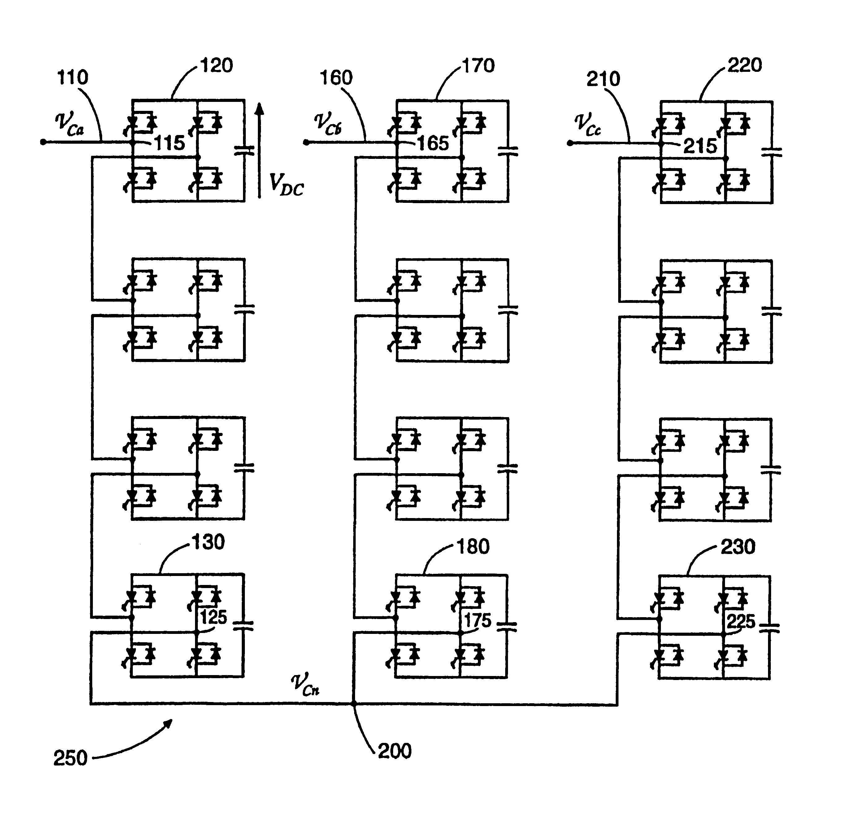
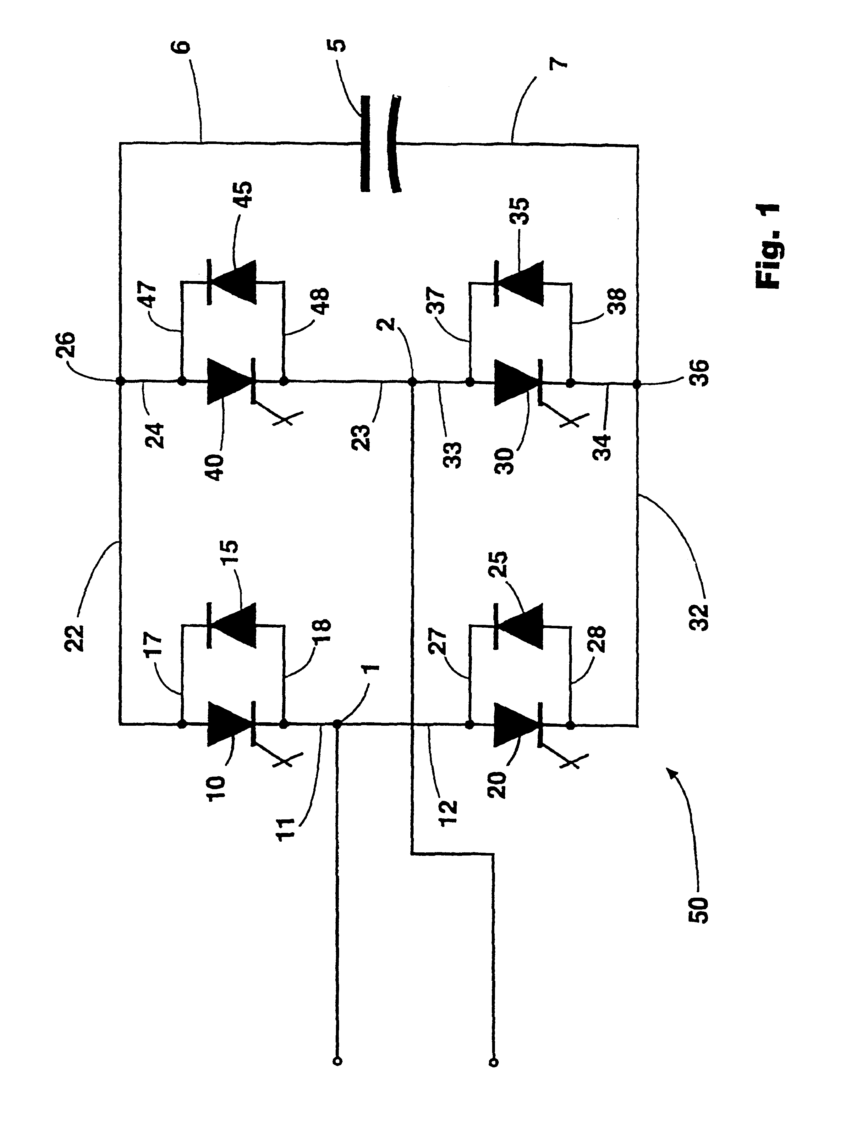
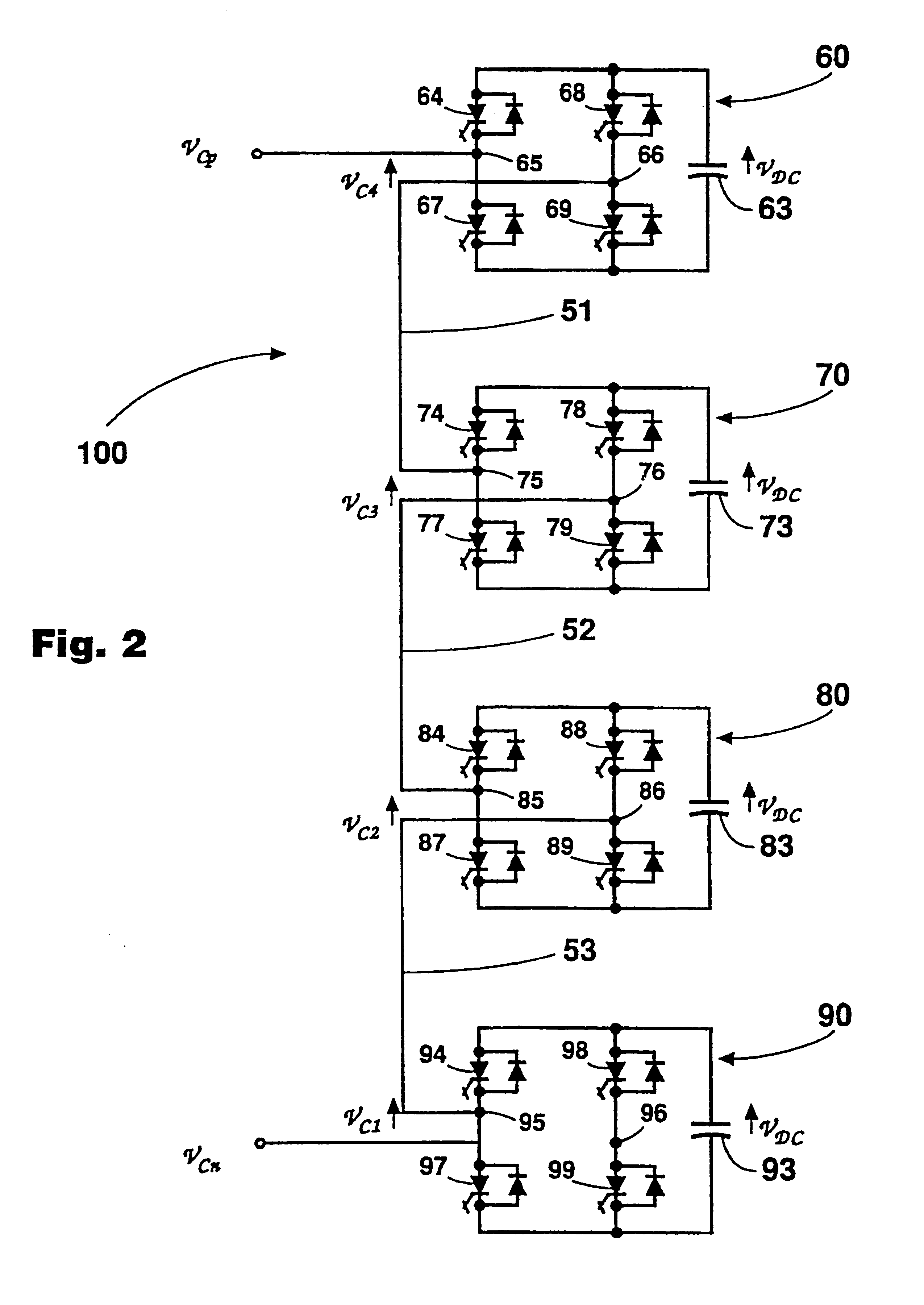
SINGLE-PHASE EMBODIMENT

FIG. 2 shows the single-phase embodiment 100 of the multilevel cascade inverter having separate DC voltage sources. The single-phase embodiment 100 comprises n FBI units 60, 70, 80 and 90 wherein n is determined by: ##EQU1##

wherein M is the number of output voltage levels generated by the multilevel cascade inverter during a half fundamental cycle.

FBI units 60 and 70 are interconnected between primary node 75 and secondary node 66 by conductor 51. FBI units 70 and 80 are interconnected between primary node 85 and secondary node 76 by conductor 52. FBI units 80 and 90 are interconnected between primary node 95 and secondary node 86 by conductor 53. The primary node 65 of the first FBI unit 60 in the multilevel cascade inverter functions as the output of the cascade inverter single-phase embodiment 100. The secondary node 96 of the last FBI unit 90 in the multilevel cascade inverter functions as the reference of the cascade inverter single-phase embodiment 100. ...

example

An SVG system using the delta connected embodiment of a 21-level cascade inverter having 10 FBI units per phase is connected directly to a 13 kV distribution system. The SVG capacity is .+-.50 MVAR. I.sub.SVG =2.22 kA, I=1.282 kA, L.sub.C =3%, MI.sub.min =0.6385, MI.sub.max =0.8054, V.sub.dc =2 kV and .epsilon.=.+-.5%. At the rated load of +50 MVAR, [.theta..sub.1, .theta..sub.2. . . .theta..sub.i ]=[0.0334, 0.1840, 0.2491, 0.3469, 0.4275, 0.5381, 0.6692, 0.8539, 0.9840, 1.1613] rad. For this SVG system, the total required capacitance of DC capacitors can be calculated as C=370 mF. The required capacitance for a comparable conventional multipulse inverter will be C.sub.dc =332 mF. Therefore, the ratio C / C.sub.dc approached unity at 1.11.


PUM


Abstract

A multilevel cascade voltage source inverter having separate DC sources is described herein. This inverter is applicable to high voltage, high power applications such as flexible AC transmission systems (FACTS) including static VAR generation (SVG), power line conditioning, series compensation, phase shifting and voltage balancing and fuel cell and photovoltaic utility interface systems. The M-level inverter consists of at least one phase wherein each phase has a plurality of full bridge inverters equipped with an independent DC source. This inverter develops a near sinusoidal approximation voltage waveform with only one switching per cycle as the number of levels, M, is increased. The inverter may have either single-phase or multi-phase embodiments connected in either wye or delta configurations.

Description

FIELD OF THE INVENTIONThe present invention relates to a multilevel voltage source inverter with separate DC sources, and more particularly to a multilevel voltage source inverter with separate DC sources including an apparatus and a method for use in flexible AC transmission system (FACTS) applications such as compensating reactive power and voltage balancing.BACKGROUNDWith long distance electrical power transmission and load growth, active control of reactive power (VAR) is indispensable with regard to stabilizing power systems and maintaining supply voltages. Static VAR generators (SVGs) using voltage-source inverters have been widely accepted as the next generation of reactive power controllers for power systems replacing conventional VAR compensators such as Thyristor Switched Capacitors (TSCs) and Thyristor Controlled Reactors (TCRs).Delivering power from a power generating station to the ultimate power consumers over long transmission lines can be very costly for an electric ...

Claims


Application Information

Patent Timeline
IPC IPC(8): H02M7/48H02M7/49
CPCH02M7/49H02M2007/4835Y02E40/26H02J3/1857Y02E40/12Y02E10/56Y02E40/10Y02E40/20H02M7/4835
Inventor PENG, FANG ZHENGLAI, JIH-SHENG
Owner LOCKHEED MARTIN ENERGY SYST INC
Why Eureka
Try Eureka